
Instruction Manual


Pointe Controller User Guide Appendix C: Ladder Diagram Block Reference
377
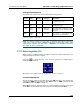
Functional Description
This block always passes the Enable input state (EN) through to the Enable Out
output state (ENO) without change; when EN becomes on, ENO is turned on, and
when EN becomes off, ENO is turned off.
When EN becomes on, the block function is executed: the Input Value 1 (IN1) is
raised to the power of the Input Value 2 (IN2) and the result is placed in the
Output Value (OUT).
The block function is executed every time the ladder is scanned, so long as EN
remains on. If EN becomes off, then OUT remains at its last calculated value until
EN becomes on and the block function is executed again.
Configuration Reference
The parameters of this block are described in the following table:
Param Name Config Var Type Description
EN Enable no - The state of the rung (off/on)
received from the left.
ENO Enable
Out
no - The state of the rung (off/on)
passed to the right.
IN1 Input
Value 1
req real only*
Numeric
The base input value. If a Numeric
value is manually entered, it must
be real / floating.
IN2 Input
Value 2
req real only*
Numeric
The exponent input value. If a
Numeric value is manually entered,
it must be real / floating.
OUT Output
Value
req real only* The result of raising the base input
value to the exponent input value.
* Any 32-bit Real (F) Input, Output, or Memory tag. For more information, see “Defining Input,
Output, Memory tags” on page 114.
NOTE: This function does not check for bit register overflow. If overflow occurs,
the value “1.#INF00” (infinite) is placed in the output.