
Instruction Manual

Appendix C: Ladder Diagram Block Reference Pointe Controller User Guide
346
Configuration Reference
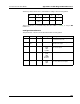
The parameters of this block are described in the following table:
Param Name Config Var Type Description
EN Enable no - The state of the rung (off/on)
received from the left.
ENO Enable
Out
no - The state of the rung (off/on)
passed to the right.
CLK Clock req %IX
%MX
%QX
T_DONE
The input value.
Q Output req %IX
%MX
%QX
The output value that is triggered
when the input value transitions
from 0 to 1.
C.1.13 Set-Dominant Bistable (SR)
When used in a Ladder Diagram, the SR block switches an output bit between 0
and 1 depending on the values of two input bits. The block is “set-dominant,
meaning that a decision to set the output bit to 1 will override a decision to reset
the output bit to 0.
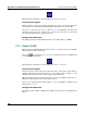
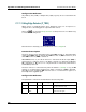
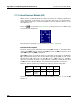
Select the
tool (from the Relays and Coils toolbar) and click on a ladder rung
to insert the following block:
Once the block is inserted, you can double-click on it to configure it.
Functional Description
This block always passes the Enable input state (EN) through to the Enable Out
output state (ENO) without change; when EN becomes on, ENO is turned on, and
when EN becomes off, ENO is turned off.
When EN becomes on, the block function is executed: a new value for the Output
(Q) is determined based on the Set and Reset inputs (S1 and R), as well as the
existing value of Q. If S1 is true or 1, then Q is set to 1. If R is true or 1, then Q is
reset to 0. (However, the block is set-dominant, so S1 will override R.) If both S1
and R are false or 0, then Q is left at its existing value regardless of what it is.