
Instruction Manual

Pointe Controller User Guide Appendix C: Ladder Diagram Block Reference
345
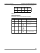
Param Name Config Var Type Description
CLK Clock req %IX
%MX
%QX
T_DONE
The input value.
Q Output req %IX
%MX
%QX
The output value that is triggered
when the input value transitions
from 1 to 0.
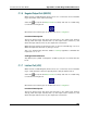
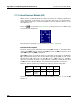
C.1.12 Rising Edge Detector (R_TRIG)
When used in a Ladder Diagram, the R_TRIG block waits for an input bit to
change from 0 to 1 and triggers an output bit when it does.
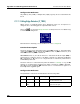
Select the tool (from the Relays and Coils toolbar) and click on a ladder rung
to insert the following block:
Once the block is inserted, you can double-click on it to configure it.
Functional Description
This block always passes the Enable input state (EN) through to the Enable Out
output state (ENO) without change; when EN becomes on, ENO is turned on, and
when EN becomes off, ENO is turned off.
When EN becomes on, the block function is executed: the Clock input (CLK) is
monitored for a transition from 0 to 1. When a transition is detected, the Output
(Q) is triggered; i.e., Q is set to 1 for a single execution of the block, after which it
is immediately reset to 0.
The block function is executed every time the ladder is scanned, so long as EN
remains on. However, Q is triggered only when a transition in CLK is detected.
After Q has been triggered, CLK must be reset to 0 and transition again to 1
before Q can be triggered again.