
Instruction Manual

Pointe Controller User Guide Appendix C: Ladder Diagram Block Reference
341
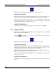
C.1.6 Negated Output Coil (NEGOC)
When used in a Ladder Diagram, this block acts as a coil that sets an associated Bit
tag to the inverse of the state of the rung.
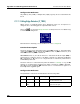
Select the
tool (from the Relays and Coils toolbar) and click on a ladder rung
to insert the following block:
Once the block is inserted, you can double-click on it to configure it.
Functional Description
This block always passes the input state through to the output state without
change; when the input state becomes on, the output state is turned on, and
when the input state becomes off, the output state is turned off.
When the input state from the left becomes on, the associated Bit tag is set to 0.
When the input state becomes off, the tag is set to 1.
The coil is checked every time the ladder is scanned, regardless of whether the
input state is on or off.
Configuration Reference
Any Memory Bit (%MX) or Output Bit (%QX) tag may be associated with the
block.
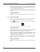
C.1.7 Latched Coil (LOC)
When used in a Ladder Diagram, this block acts as a coil that sets an associated Bit
tag to 1 and maintains it until it is explicitly reset to 0 by an external action.
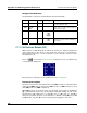
Select the tool (from the Relays and Coils toolbar) and click on a ladder rung
to insert the following block:
Once the block is inserted, you can double-click on it to configure it.
Functional Description
This block always passes the input state through to the output state without
change; when the input state becomes on, the output state is turned on, and
when the input state becomes off, the output state is turned off.