
Instruction Manual


Appendix A: OptiLogic Technical Specifications Pointe Controller User Guide
276
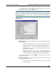
A.12 OL2408 Analog Voltage Input
The OL2408 Analog Voltage Input Module provides eight (8) voltage sensors.
Each sensor reads the current input voltage, scales it, and writes the scaled value
to a Logic Memory tag. The value has 14-bit resolution and is scaled from 0 to
16383 (0x0 to 0x3FFF); i.e., the minimum voltage is equal to 0, the maximum
voltage is equal to 16383, and all other voltages are scaled in between.
NOTE: The OL2408 comes factory configured for 0-5VDC input range and cannot
be changed through software. If you need 0-10VDC input range, you must
physically set a jumper on the module board.
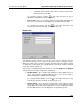
To convert the scaled value back to an actual voltage input, you must configure a
Flow Chart block or Ladder Logic rung to perform the following calculation:
Voltage Input = Maximum Voltage x ( Scaled Value / 16383 )
Remember that Maximum Voltage can be either 5 or 10, depending on the
jumper setting.
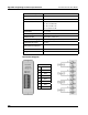
Technical Specifications
Card Cage Power Required 700 mA
Inputs 4
Input Type 0-5 VDC or 0-10 VDC
Input Impedence 10 MOhm
Maximum Voltage Input +/- 15VDC
Conversion Type Successive approximation
Resolution 14 bit (1 in 16384)
Full Scale Calibration Error +/- 15 counts maximum
+/- 5 counts typical
Offset Calibration Error +/- 2 counts maximum
Linearity Error +/- 1.25 count maximum
Input Stability +/- 2 counts
Terminal Strip Plug In (removable)
Terminal Screws Slotted (0.1” blade max.)
Max. terminal wire gauge 18 AWG (use copper conductors)
Terminal block torque 2.2 lb-in
Required Temp. rating of
field installed conductors
60°C / 75°C
Type 17