
Instruction Manual

Pointe Controller User Guide Appendix A: OptiLogic Technical Specifications
259
The count can be reset to 0 at any time. Again there is both a reset message that
can be sent from the PC and an optional hardware reset signal.
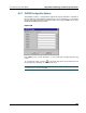
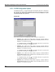
Whether the hardware “reset” and “enable” are used is determined by how the
module is configured in the PointeControl development framework (see below).
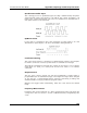
Input Signal
The input pulse train is a repetitive square wave input that looks something like
the following:
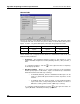
If you know the maximum frequency of the pulse train, you can configure the
pulse counter to count pulse up to that pulse rate. In doing so, the counter will
consider anything above the maximum rate that you have defined to be noise
and will ignore it.
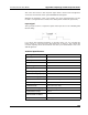
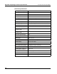
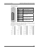
Technical Specifications
Card Cage Power Required 100 mA
Inputs (all) 8
Pulse Inputs 2
Status Indicators Logic Side LED
Input Voltage 10 – 30 VDC
Input Impedence 2.7K ohms
Input frequency (on pulses) 15 KHz maximum
Min. On Current (per point) 3.3 mA
Max. On Current (per point) 11 mA
Commons 2 (connected internally)
Terminal Strip Plug In (removable)
Terminal Screws Slotted (0.1” blade max.)
Max. terminal wire gauge 18 AWG (use copper conductors)
Terminal block torque 2.2 lb-in
Required Temp. rating of
field installed conductors
60°C / 75°C
Weight 1.2 oz (34g)