
Instruction Manual


Pointe Controller User Guide Chapter 5: Developing Controller Programs
127
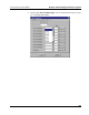
5.5.2 Configuring I/O modules
For each I/O module that you have specified as being installed in your Pointe
Controller unit, you must configure that module’s individual settings and I/O
points to work with your project. The configuration options are accessed by
clicking on the I/O button to the right of the module.
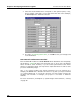
NOTE: All of the tags for a given module must already be defined in Logic
Memory before you can associate them with the module’s I/O points. If the tags
are not defined or if you’re not sure what tags are required, review the module
below and then go back to Defining Variables in Logic Memory.
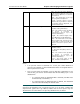
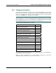
Select an OptiLogic I/O module to configure:
MODULE GO TO…
OL2104 Relay Output Module Page 233
OL2108 Relay Output Module Page 236
OL2109 DC Sinking Output Module Page 240
OL2111 AC Solid-state Relay Module Page 244
OL2201 Digital Input Simulator Module Page 248
OL2205 AC/DC Digital Input Module Page 250
OL2208 DC Digital Input Module Page 254
OL2211 AC Digital Input Module Page 256
OL2252 Dual Pulse Counter Module Page 261
OL2258 High Speed Counter Module Page 268
OL2304 Analog Voltage Output Module Page 273
OL2408 Analog Voltage Input Module Page 276
OL2418 Analog Current Input Module Page 279
OL2602 Dual Serial Port Module Page 282
For complete technical descriptions of all of these modules, see Appendix A,
“OptiLogic Technical Specifications.”
When you have configured all of the I/O modules installed in your Pointe
Controller unit, proceed to Configuring operator panels.