
Manual


Optimation, Inc.
(256)883-3050 29
www.optimate.com
OptiLogic Series
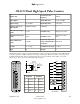
OL2408 Analog Voltage Input Module
Inputs 8 Power required 700mA
Input Type
0-5 VDC or
0-10VDC
Conversion Type Successive approximation
Resolution 14 bit (1 in 16384)
Full Scale Calibration
Error
+/- 15 counts max.
+/- 5 counts typical
Input Impedance 10 MOhm
Offset Calibration error
+/- 2 counts max.
Maximum Voltage
Input
+/- 15VDC
Max. Terminal wire
gauge
18 AWG (use copper
conductors)
Linearity error +/- 1.25 count max Terminal Strip Plug In (removable)
Input stability +/- 2 counts Terminal Screws Slotted (0.1” blade max.)
Terminal block
torque
2.2 lb-in
Required Temperature
rating of field installed
conductors
60C/75C
Type 17 Subtype 1
1
2
4
5
6
7
8
9
10
3
L
O
2408
Analog
Voltage
Input
10
9
8
7
6
5
4
3
2
1
0-5 VDC
or 0-10 VDC
0-5 VDC
or 0-10 VDC
0-5 VDC
or 0-10 VDC
0-5 VDC
or 0-10 VDC
0-5 VDC
or 0-10 VDC
0-5 VDC
or 0-10 VDC
0-5 VDC
or 0-10 VDC
0-5 VDC
or 0-10 VDC
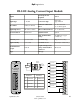
Terminal Terminal
1 Common 6 Channel 4
2 Common 7 Channel 5
3 Channel 1 8 Channel 6
4 Channel 2 9 Channel 7
5 Channel 3 10 Channel 8
The OL2408 comes set up for 0-5VDC input range. If you need 0-10VDC input range, you must remove the plastic
module cover by lifting the board latches over the retainer hooks on the PC board. Then, place the jumper on both
pins of J2 and replace the plastic module cover. To change back to 0-5VDC range, repeat the process and remove
the jumper. Having the cover over the range selector jumper ensures that it will not be inadvertantly changed.