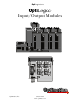
OptiLogic Series OptiLogic Input/Output Modules Optimal Automation for Industry Optimation, Inc. (256)883-3050 www.optimate.
OptiLogic Series WARNING Thank you for purchasing industrial control products from Optimation, Inc. We want your new system to operate safely. Anyone who installs or uses this equipment should read this manual (and any other relevant publication) before installing or operating the system. To minimize the risk of potential safety problems, you should follow all applicable local and national codes that regulate the installation and operation of your system.
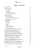
OptiLogic Series Introduction . Digital Inputs . . . . . Digital Outputs . . Analog Inputs . . . . . Input Isolation . . DC Inputs . . . AC Inputs . . . Digital Input Voltage . I/O “Common” Terminals . . . . . . . . . . . 6 7 . . . . . . . . . . . . . . . . . . . . 7 7 8 8 8 . . . . . 11 . . . . . . . . . . . . . . . . . . . . . . . . . . . . . . . . OL2104 Isolated Relay Output Module . OL2108 Relay Output Module . . . OL2109 DC Sinking Output Module .
OptiLogic Series OL2602 Dual RS232 Module Optimation, Inc. . . (256)883-3050 www.optimate.com . . .
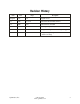
Revision History Issue Date Pages Description Original 8/99 1-24 Original release 1.1 1/00 13, 18, 25 Added OL2104, OL2205, OL2418 1.2 9/00 25-28 Added OL2258, OL2304 1.3 04/01 various Added specs requested by UL 1.4 09/02 15 Changed wording of OL2108 voltage rating spec 1.5 10/2012 14, 15 Changed voltage ratings of OL2104 and OL2108 to match UL ratings Optimation, Inc. (256)883-3050 www.optimate.
OptiLogic Series OptiLogic Input/Output Modules Introduction Optimation’s OptiLogic series is a flexible, modular system, designed to allow you the ability to configure an optimal solution for your exact needs. To accomplish this goal, Optimation has developed a series of I/O modules, communications modules, specialty modules and operator panels that can be plugged together in nearly any combination. This manual covers the currently available modules that plug into the card cage.
Digital Inputs OptiLogic Series Digital I/O modules are used to either monitor (input) or control (output) the “state” of something. “State” being on or off, active or inactive, open or closed - etc. In the “real world” digital I/O requirements come in a variety of shapes and sizes. Therefore, there are a variety of available modules designed to meet the variety of needs.
OptiLogic Series AC Inputs maximum voltage corresponds to the maximum current the optocoupler can handle without AC digital inputs are typically supplied being damaged. either directly from line voltage or transformed down from line voltage. The most common AC I/O “Common” Terminals inputs are 120VAC and 24VAC, although any voltage range is possible. For a digital input circuit, one input terminal and one output terminal is necessary for A typical AC input circuit is shown operation.
Digital Outputs OptiLogic Series Relay Loads Relays are affected by the type of load Digital outputs are used to turn “loads” that is switched. Inductive loads (solenoids, on and off. “Loads” may be lights, motors, motors, etc.) tend to wear the relay much more solenoids, or any type of on/off device found in than resistive loads (lights, heaters, etc.). the “real world”.
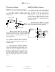
OptiLogic Series Transistor Outputs Solid State Relay Outputs NPN Transistor Sinking Outputs Solid state relays are semiconductor switches that operate very much like mechanical An NPN transistor sinking output relays. They have an advantage over mechanical provides a path to ground. A typical circuit is relays by virtue of the fact that they are semiconductors. Solid state relays can be shown below. switched at relatively high frequencies and they do not wear out.
Analog Inputs OptiLogic Series Analog inputs are used to monitor the value of some continuously variable measurement. Typical analog inputs are measurements of temperature, pressure, weight, liquid level, pH, flow rate and many other “real world” parameters. also use the main power supply and isolated power via a switching power converter and a transformer. There are OptiLogic analog input modules in both categories. Neither is functionally superior to the other.
OptiLogic Series Resolution Range Resolution is the number of significant bits of information the A/D converter uses to express the value of the measured input. A 12-bit A/D converter uses 12 bits of information, meaning the entire range is covered by a number between 0 and (2(12)-1) or 0 to 4095. A 14-bit A/D expresses the same range as a number between 0 and 16,383. In other words, the more bits used, the finer the increment. In general terms, the higher the resolution, the better.
OptiLogic Series Single Ended Inputs Differential Inputs Single ended inputs are all referenced to the same ground point. In many applications, single ended inputs produce significant advantages. Single ended inputs require only one ground connection and one signal input per measured value. The result is reduced wiring costs along with the reduced cost per channel on the analog input module. There are cases when the individual analog inputs cannot be connected to a common ground.
OL2104 Relay Output Module Outputs 4 Card Cage Power Required 215 mA Output Type Mechanical relay Contact resistance 0.1 ohm (initial) Status Indicators Logic Side LED Terminal Strip Plug In (removable) Contact voltage rating Contact rating 0 - 24 VDC 0 - 120 VAC 1A (resistive)/point @24 VDC, 1A/point @120 VAC, 1A/point Contact type Form A (SPST) Terminal Screws Slotted (0.
OL2108 Relay Output Module Outputs 8 Card Cage Power required 375 mA Output type Mechanical relay Contact resistance 0.1 ohm (initial) Status Indicators Logic Side LED Contact rating 1A (resistive)/point @24 VDC, 1A/point @120 VAC, 1A/point Terminal Strip Plug In (removable) Contact type Form A (SPST) Terminal Screws Slotted (0.1î blade max.) Minimum load 10 mA Maximum Terminal Wire Gauge 18 AWG (use copper conductors) Contact arrangement 4 relays per common Terminal block torque 2.
OptiLogic Series OL2109 DC Sinking Output Module Outputs 8 Card Cage Power required 140 mA Output Type NPN open collector transistor Status indicators Logic side LED Voltage Rating 0 - 40VDC Peak Voltage 80VDC Terminal strip Plug In (removable) On voltage drop .75V @ 100mA .95V @ 300mA Commons 2 (connected internally) Terminal screw Slotted (0.1” blade max) Maximum continuous load current 300 mA Maximum terminal wire gauge 18 AWG (use copper conductors) Maximum surge current 1.
OptiLogic Series OL2111 AC Solid State Relay Module Outputs 8 Card Cage Power required 120 mA Output Type SSR (Trice) Commons 2 (connected internally) Voltage Rating 12 - 132 VAC Status indicators Logic side LED Max. load current .5A/point @ 120VAC Min. load current 10mA Terminal Strip Plug In (removable) On state voltage drop 1V (typical) Terminal screws Slotted (0.1” blade max.
OptiLogic Series OL2201 Digital Input Simulator Module Inputs 8 Card Cage Power Required 60mA Input Type Toggle Switch Status Indicators Logic side LED Weight 1.1 oz (30 g) Subtype 3 Type 1 The OL2201 Digital Input Simulator Module is designed to be an aid to program development. Use the OL2201 to simulate real world inputs during your design and debug process. The OL2201 enables the program developer to cause a change in input status at will to simulate a system action.
OptiLogic Series OL2205 AC/DC Input Module Inputs 4 Card Cage Power Required 60mA Input Type AC Optocoupled Status Indicators Logic Side LED Voltage Range 10-30 V AC or DC Input Impedence 2.7K Min. On Current (per point) 3.3 mA Inputs DC sinking or sourcing / or AC Max. On Current (per point) 11 mA Terminal Strip Plug In (removable) Terminal Screws Slotted (0.1” blade max.) 60C/75C Max.
OptiLogic Series OL2208 DC Digital Input Module Inputs 8 Card Cage Power required 60mA Input Type DC Optocoupled Status Indicators Logic side LED Voltage Range 10 - 30 VDC Input Impedance 2.7K Min. On Current (per point) 3.3 mA Max. On Current (per point) 11 mA Commons 2 Terminal Strip Plug In (removable) Max. Terminal wire gauge 18 AWG (use copper conductors) Terminal screw Slotted (0.1” blade max.) Required Temperature rating of field installed conductors 60C/75C Weight 1.
OptiLogic Series OL2211 AC Digital Input Module Inputs 8 Card Cage Power Required 60 mA Input Type AC Optocoupled Status Indicators Logic side LED Voltage Range 80 - 132 VAC Input Impedance 47K Min. On Current (per point) 1.7 mA Commons 2 (connected internally) Max. On Current (per point) 2.8 mA Terminal Strip Plug In (removable) Terminal Screws Slotted (0.1” blade max.
OptiLogic Series OL2252 Dual High Speed Pulse Counter Inputs (all) 8 Card Cage Power Required 100 mA Pulse Inputs 2 Status Indicators Logic side LED Input Voltage 10 - 30 VDC Input Impedance 2.7K ohms Input frequency (on pulse inputs) 15 KHz maximum Commons 2 Min. On Current (per point) 3.3 mA Terminal Strip Plug In (removable) Max. On Current (per point) 11 mA Terminal Screws Slotted (0.1” blade max.
OptiLogic Series OL2252 Dual Pulse Counter cont’d The OL2252 Dual Pulse input module is Theory of Operation designed to provide two independent pulse counting inputs. Each input is independent of The OL2252 Pulse Counter has two the other. There are also a number of independent pulse counter inputs. These pulse configuration options available. counter inputs will accurately count pulses between 0 and 15KHz. The following is a list of the input connections.
OptiLogic Series OL2252 Pulse Input cont’d Input Signal The input pulse train is a repetitive square wave input that looks something like the following. 1 count If you know the maximum frequency of the pulse train, you can configure the pulse counter to count pulse up to that pulse rate. In doing so, the counter will consider anything above the maximum rate that you have defined to be noise and will ignore it. Optimation, Inc. (256)883-3050 www.optimate.
OptiLogic Series OL2258 High Speed Pulse Counter Inputs (all) 4 Card Cage Power Required 100 mA Pulse Inputs 2 Status Indicators Logic side LED Input signal type Sinking, sourcing or differential Input Impedance 2.0K ohms nominal Input frequency (on pulse inputs) 80/160 KHz maximum Count value 32 bit signed integer Min. Input On Voltage (or differential) 16 bit signed integer 4.00V Frequency data (Configurable for 1 second or 200 mS count) Pulse & Direction Max.
OptiLogic Series OL2258 High Speed Pulse Counter cont’d Interfacing the OL2258 A B LS L 1 2 Outs The OL2258 High Speed Pulse counter is designed to interface to a variety of standard pulse encoder devices. The electrical interface is shown on the right. P U Z OL 2258 7 6 5 7 4 3 L1 LS Z B A Optimation, Inc. 10 L2 9 L1 8 7 6 5 4 3 2 1 LS encoder ground Z B A 10 7 6 5 4 3 2 1 Z B A (256)883-3050 www.optimate.
OptiLogic Series OL2258 High Speed Pulse Counter cont’d Pulse and Direction Z and LS Presetting In this configuration, pulses are input to The count can be preset to a value that “A”. The counter direction is controlled by input you define based on either or both inputs LS and “B”. The operation is illustrated below. Z. It can also be forced to a preset value on command via a message.
OptiLogic Series OL2304 Four Channel Voltage Output Outputs Output Ranges 4 0-5V, 0-10V, +/-5V, +/-10V (individual channel configurable) Card Cage Power required 700mA External Power required none Resolution 12 bit (1 in 4096) Output current +/-5mA Output type Single ended, 1 common Short circuit current +/-15mA Max terminal wire gauge 18 AWG (use copper conductors) Offset calibration error +/-8 counts @ +/-10V +/-16 counts @ +/-5V +/-16 counts @ 0-10V +/- 32 counts @ 0-5V Nonlinearity +
OptiLogic Series OL2408 Analog Voltage Input Module Inputs 8 Power required 700mA Input Type 0-5 VDC or 0-10VDC Conversion Type Successive approximation Resolution 14 bit (1 in 16384) Full Scale Calibration Error +/- 15 counts max. Input Impedance 10 MOhm Offset Calibration error +/- 2 counts max. Maximum Voltage Input +/- 15VDC Max. Terminal wire gauge 18 AWG (use copper conductors) Linearity error +/- 1.
OptiLogic Series OL2418 Analog Current Input Module Inputs 8 Card Cage Power Required 700mA Input Type 4 - 20 mA Conversion Type Successive approximation Resolution 14 bit (1 in 16384) Full Scale Calibration Error +/- 15 counts max. +/- 5 counts typical Input Impedence 250 ohm +/- 0.05% Offset Calibration Error +/- 2 counts max. Power Isolation Transformer Signal Isolation Optical Max. Terminal Wire Gauge 18 AWG (use copper conductors) Linearity error +/- 1.
OptiLogic Series OL2602 Dual RS232 Module Communication Ports 2 Card Cage Power Required 110 mA Type RS232C Status Indicators LEDs for TX and RX Baud Rates 1200, 2400, 4800, 9600, 19,200 (selectable) System limitations *See below Parity Even, odd or none Max. Terminal Wire gauge 18 AWG (use copper conductors) Data bits 7 or 8 Terminal Strip Plug In (removable) Transmit buffer 48 bytes Terminal Screws Slotted (0.
OptiLogic Series Optimation, Inc. (256)883-3050 www.optimate.