ePC-Plus & nPC200 High Performance Ultra-Thin Industrial Computers User’s Guide Document No. DOC-IPC-002, User Manual ePC-Plus & nPC200, Rev D Rel.
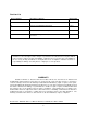
Revision List Revision Number Description of Change Release Date A Initial Release 7-2009 B Revision for Field Wiring Requirements 5-2010 C Added nPC200, -EN, and –RM options 12-2011 D UL Required changes for UL 1604 to ANSI/ISA 12.12.01-2012 Conversion 9-2012 Nematron reserves the right to make changes in specifications described herein at any time without notice in order to improve design and reliability.
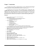
Chapter 1 - Introduction The ePC-Plus Series products are high performance color TFT embedded ultra-thin industrial computers specifically designed for harsh industrial environments. This series is an extension to the ePCSeries with added features including DVD-R/W, Dual hard drives, and PCI expansion. The ePC-Plus Series offers four versions with 15” XGA (1024 x 768), 17” SXGA (1280 x 1024), 19” SXGA (1280 x 1024) TFT Color LCD panels, or no attached LCD (nPC200).
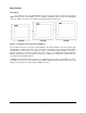
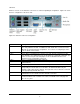
Specifications Front Panels The ePC-Plus series has NEMA 4/4X/12 sealed front panels when mounted in an appropriate NEMA rated enclosure. See Chapter 2 for more details on installation and selection of an appropriate enclosure. All three sizes have very similar front panels with different dimensions. ePC1550 ePC1750 ePC1950 Figure 1.0: ePC-Plus Series Front Panel Comparison The standard front panels are powder coated aluminum.
I/O Panel All three versions of the ePC-Plus series have a common Input/Output configuration. Figure 2.0 shows the base configuration of the three units. Figure 2.0: ePC-Plus Series I/O configuration Feature Video Port Com 1 Com 2 Com 3 Gigabit Ethernet USB 2.0 PS/2 Port Input Power SATA Hard Drive Description A standard 15-pin analog VGA is provided. This connection allows a second screen to be easily added to the ePC.
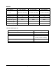
DISPLAY ePC1550 15.0” (381.0mm) ePC1750 17.0” (431.8mm) ePC1950 19.0” (482.6mm) 11.97” x 8.98” 13.30” x 10.64” 14.82” x 11.85” (304.0mm x 228.1mm) (337.8mm x 270.3mm) (376.4mm x 301.
PHYSICAL ePC1550 ePC1750 ePC1950 Over All Dimensions 12.80” x 15.80” x 4.55” 14.48” x 17.14” x 4.55” 15.70” x 18.66” x 4.70” (H x W x D) (325.1mm x 401.3mm x 115.6mm) (367.8mm x 435.4mm x 115.6mm) (398.8mm x 474.0mm x 119.4mm) Panel Mounting Depth 4.3” (109.2mm) 4.3” (109.2mm) 4.45” (113.0mm) Cutout Dimensions 12.00” x 15.00” 13.70” x 16.35” 14.90” x 17.75” (H x W) (305mm x 381mm) (348mm x 415.3mm) (378.5mm x 450.9mm) Weight 20.0 lbs (9.07kg) 24.0 lbs (10.88kg) 28.0 lbs (12.
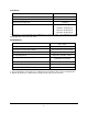
ELECTRICAL AC Input Voltage 100 – 240 VAC, 47-63 Hz AC Input Current 2.0 A Maximum DC Input Voltage (Optional) 18 – 36 VDC DC Input Current (Optional) 7.5 A Max Input Power nPC200 – 60 W Typical* ePC1550 - 70 W Typical* ePC1750 – 80 W Typical* ePC1950 – 90 W Typical* * Typical Power is measured without any additional I/O or expansion options. Any additional I/O installed during application can increase this value.
AGENCY Front Panel NEMA Rating NEMA 4/4X/12, IP65 FCC 47 CFR, Part 15, Class A EU CE Marking Compliance CE, EN 55022: Class A, EN 61000-3-2: Class A, EN 61000-3-3, EN 61000-6-2, Safety Agency Approvals UL 508 Listed, ANSI/ISA 12.12.012012 Listed*, cUL Listed CSA C22.2, #142, CSA C22.2, #143* * See appropriate note below for the applicable unit or option being utilized.
NOTE (RACK MOUNT VERSIONS): SUITABLE FOR USE IN CLASS I, DIVISION 2, GROUPS A, B, C AND D, CLASS II DIVISION 2, GROUPS F AND G, CLASS III HAZARDOUS LOCATIONS, OR NONHAZARDOUS LOCATIONS ONLY FOR RACK MOUNT INSTALLATION ON A TYPE 1 ENCLOSURE WITH PROVISIONS FOR CLASS I DIVISION 2 WIRING METHODS TEMPERATURE CODE: T5 NOTE: (ENCLOSED EPC VERSIONS): A LISTED VESA STYLE MOUNT SUITABLE WITH A MINIMUM LOAD RATING OF 40 POUNDS SHALL BE USED IN THE END INSTALLATION FOR USE IN NONHAZARDOUS LOCATIONS ONLY TYPE 1 ENCLOS
Chapter 2 - Installation of Computer The panel mount versions of the ePC-Plus units are intended to be mounted in and used where NEMA 1, NEMA 4/4x and NEMA 12 type enclosures are employed. Enclosures made of heavier gauge metal work better because they won’t deform or bend as easily when the monitor’s sealing gasket is compressed. The monitor meets NEMA 4/12 sealing specifications when properly installed in an approved NEMA enclosure constructed from 14-gauge or heavier steel.
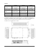
Cutout Pattern for ePC1750 / ePC1750T Industrial Computer 13.70" ±.02" 16.35" ±.02" Cutout Pattern for ePC1950 / ePC1950T industrial Computer 14.90" ±.02" 17.75" ±.
Mounting Clip Installation .25" THICK MONITOR FRONT BEZEL COMPRESSABLE NEMA SEALING GASKET MOUNTING CLIP WITH 10x32 SCREW .325" MAXIMUN ALLOWABLE PANEL THICKNESS CUT AWAY FRONT PANEL OF NEMA ENCLOSURE TIGHTEN TO 8 INCH-POUNDS FRONT PANEL OF NEMA ENCLOSURE MENU SELECT DOWN UP POWER REAR VIEW OF PANEL MOUNTED ePC-Plus NOTE: WHEN INSTALLING THE MOUNTING CLIPS TIGHTEN THE SCREWS TO 8-10 INCH-POUNDS MAXIMUM.
nPC200 Unit Installation The nPC200 is intended to be mounted on the flat surface on the inside of a NEMA Type 1, 4/4x or NEMA 12 enclosure. See the specifications section for the dimensions and mounting dimensions required for mounting this unit. When selecting an enclosure remember to allow adequate space around the computer for good air flow. Do not block air flow around the unit except for the mounting surface.
Connecting Power to the ePC-Plus Connecting power to the Panel Mount, Rack Mount, and nPC120 units: The ePC-Plus and nPC200 units are powered from 100-240 VAC, 50/60 Hz or optionally from 24 VDC. Damage will occur if 100-240 VAC power is connected to an ePC-Plus unit equipped with the 24 VDC input power option. ePC-Plus equipped units with the 24 VDC option will have a “-DC” suffix in their model number such as ePC1550-MC5500-1GB-HD-DVD-XP-DC or ePC1550T-T7500-2GB-HDDVD-XP-DC.
NOTE: WHEN USING USB CONNECTIONS THE USE OF THE USB RETENTION BRACKET IS REQUIRED FOR HAZARDOUS LOCATIONS AND HIGHLY RECOMMENDED FOR NONHARDAOUS LOCATIONS. NOTE: TO PREVENT INADVERTENT DISCONNECTION OF VIDEO AND/OR SERIAL TOUCHSCREEN CABLES ASSURE THAT THE THUBSCREWS ARE SUFFICIENTLY TIGHTENED. WARNING – EXPLOSION HAZARD – DO NOT DISCONNECT EQUIPMENT WHILE THE CIRCUIT IS LIVE OR UNLESS THE AREA IS KNOW TO BE FREE OF IGNITABLE CONCENTRATIONS.
Protective Cover Installation (Optional if desired) Step 1: Gather the parts of the protective cover; top shell, bottom shell, label insert, and wire tie. The picture shows wire tie (top), label insert (right), bottom shell (left), and top shell (lower right). Step 2: Insert your pre-wired connector (with the screws facing up) into the bottom shell. (See manual for cable wiring instructions).
The enclosed ePC-Plus units are powered from 100-240 VAC, 50/60 Hz only. Because these are stand alone Type 1 devices and do not require an additional NEMA type enclosure, a different type power connection is required. These units use a more standard IEC type power cord like found on most computers. There is a retention clip that can be utilized to help retain the cord from falling out. A US three prong cord is supplied.
Video and the Serial connections have jack screws in the connectors that can be utilized to secure your cable end to the unit. Ethernet connections have a plastic tab that prevents the connection from falling out. The keyboard/mouse port (splitter provided) is not secured and is intended for setup and maintenance only when in an area that is known to be nonhazardous. See the connecting power section for details on securing the power connections.
Hard Drive Removal and Replacement These products are equipped with an easily removable SATA hard drive. They are designed so that there is no need to remove the cover on these units to change a hard drive. The only reason to remove the cover will be to switch the configurable serial port from RS-485 to RS-422. See the appropriate board manual included on the “Documentation and Driver” disk for procedure on changing this port.
Installing the Touch Screen Driver Software If your ePC is ordered with a touchscreen and an operating system the drivers will be preinstalled. The ePC-Series utilizes a USB connection for the touchscreen, therefore the touchscreen will only function with operating systems that can recognize and utilize USB connections. The driver included with these units functions with Windows 2000, XP, VISTA, and Windows 7.
Chapter 3. – ePC-Plus CPU and BIOS Consult the ePC-Plus Series CPU Board User manual for more detailed specifications of the CPU board and BIOS details. This section will concentrate on the features of the ePC-Plus Series units that are externally accessible. In addition any internal details that may need adjusting will be discussed. External I/O Connections The following figure shows the externally accessible connections.