
User's Manual

14
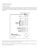
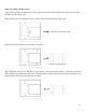
CABINET DISABLE - These four DIP switches numbered 1, 2, 3 & 4 are used to DISABLE cabinets not being
used. To DISABLE a cabinet switch should be to the LEFT. Default is set with all switches to the RIGHT.
1
4
3
2
MESSAGE TIMER - These four DIP switches, numbered 3, 8, 13 & 15 are used to control the time before a
trigger on CH2 (Channel 2) is sent to the receiver for instant trigger. CH2 on this cabinet application is connected
to the door switches. When a door is left open longer than the time in seconds set by the DIP switch, a signal is
sent to the receiver to play a message. Only one DIP switch should be set at a time. ON is to the LEFT. Default is
set with 8 (seconds) switch to the LEFT.
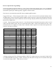
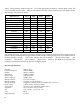
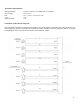
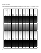
MESSAGE SELECT - These eight DIP switches, lettered A through H are used to set the message trigger that
will be sent to the receiver when an alert condition is activated. Each channel (CH1 & CH2) have their own
independent settings and can trigger any 1 of the 255 messages stored on the receiver. ON is to the LEFT. Default
onCH1is“A”settoON.DefaultonCH2is“D”settoon.PleaseseeMESSAGESELECTCHARTformessage
settings.
TEST - These two push-button tact switches are used to test both the transmitter triggering functions and in
conjunctionwiththeaboveSTATUSLED’stestthecableconnections.
Pushing the CH1 TEST button with the transmitter installed in the cabinet or as a stand-alone device will send an
instant trigger to the receiver based upon the corresponding MESSAGE SELECT switches.
Pushing the CH2 TEST button is used for testing continuity of the door cable connection and if the connections
are good and the doors are closed, then you will be able to trigger the receiver.
STATUS-ThesetwoLED’swhenusedinconjunctionwiththeTESTswitcheswillindicatecircuitcontinuity.
TotestthecabinetPUSHbutton-PressinthePUSHbuttononthecabinetandholddowntheTESTbuttononthe
transmitter module for CH1. If the cable and circuit is good, then the LED will light GREEN for 1 second.
To test the cabinet DOOR open sensor - Keep the door closed and hold down the TEST button on the transmitter
module for CH2. If the cable and circuit is good the LED will light GREEN when door is closed and turn off
when door is open.
ENABLE/DISABLE CH1 SWITCH - This switch is used to ENABLE or DISABLE CH1 without having to
remove the transmitter module from the cabinet. Looking at the transmitter from the front, ENABLE is to the
LEFT and DISABLE is to the RIGHT. When in the cabinet ENABLE would be away from you and DISABLE
would be towards you. Default is set to ENABLE.
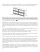
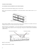
Cabinet Positions