Theft Deterrent System Electronics Package Receiver & Transmitter User Manual PLEASE LEAVE THIS MANUAL WITH THE STORE MANAGER
Index: Introduction ........................................................................................................................ 4 Receiver Instructions........................................................................................................ 5 Summary .................................................................................................................... 5 Front Panel ......................................................................................................
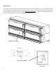
Introduction: The Alliance Theft Deterrent / In-Store Messaging System consists of two distinct parts – the mechanical package (that includes the display fixture and cabinet) and the electronics package (that includes the transmitter and receiver modules). This kit users guide covers the electronics package only - if you are having support issues with the cabinet then please refer to the users guide for the cabinet fixture.
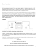
Receiver Instructions: Summary: The Receiver/Message Repeater Module is a state-of-the-art digital audio playback device with a 433MHz RF receiver designed to provide up to 255 audio messages that can be activated and played over a stores public announcement system. Messages are activated by either receiving triggering information from remote transmitters and/or by a built-in timer that will play messages on specific time intervals.
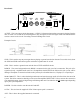
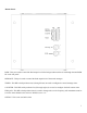
ACTIVE STOP GND Rear Panel: BGM IN 8Ω OUT 600Ω OUT ANT POWER OFF (0) 12VDC ON (1) 500mA ACTIVE - This is an output circuit that outputs +12VDC @ 25mA maximum when a message is playing from the unit. If circuit is to exceed the 25mA rating then a relay is required to drive the higher load. The GND should be used as a return on the circuit. Exceeding 25mA will damage this circuit. Example Circuits: STOP - This is used to stop any messages that are playing or queued (stacked) on the unit.
Bottom Panel: BGM - This pot is used to control the final output level of the background music that is fed through the units BGM IN on the rear panel. MESSAGE - This pot is used to control the final output level of the stored messages. TIMER - This DIP switch positions one(1) through four(4) are used to configure the stored message timer. COUNTER - This DIP switch positions five(5) through eight (8) are used to configure the theft counter timer.
Message Formatting: All messages that are available for the receiver to play are stored on an industry standard USB flash drive. Messages must be labeled correctly so they will automatically be placed into virtual message “slots” on the unit. There are three different type of message slots: 1. Triggered Message Slots – These messages reside in slots 1 to 128 of the USB flash drive and are activated instantly when a 433MHz signal is received from a transmitter. 2.
Receiver Install Summary: (See Installation Instruction Manual for more detail descriptions) Step 1: Locate the stores PA system (this is usually located in the manager’s office or a secured room in the store). The existing stores PA system will include two main parts - the background music receiver and the amplifier that feeds the stores speakers.
Step 9: Insert the USB flash drive into the front of the unit. Do not force the USB flash drive into the unit. If it does not fit in one way, try turning over and reinserting. Step 10: Turn power switch on rear of unit to the ON position. After the unit initializes the STATUS LED on front of unit will turn solid blue. This process may take up to 15 seconds. Step 11: Push the SPEAKER switch located on the front of the unit to the IN position.
Receiver Operation & Programming: The Receiver/Message Repeater Module is a state-of-the-art digital audio playback device with a 433MHz RF receiver designed to provide up to 255 audio messages that can be activated and played over a stores public announcement system by the following means; triggered, counted or timed. Note: Power to unit should be turned OFF when reconfiguring DIP switches.
Timed – These messages reside in slots 199 – 255 of the unit and are activated by a built-in timer circuit. The receiver has DIP switches (SW1 – SW4) on the bottom of the unit – these switches set the time delay between each message.
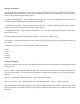
Transmitter Instructions: Summary & Operation: The Transmitter Module is a state-of-the-art 433MHz RF receiver capable of sending a 8-bit binary word to the Receiver Module. Each Transmitter Module has 2-channels that can trigger any 1 of the 255 messages on the Receiver Module. The Transmitter is battery operated and is rated at least one-year of operation under normal conditions. ENABLE/DISABLE CH1 SWITCH PWR - This switch is used to turn the power ON and OFF.
CABINET DISABLE - These four DIP switches numbered 1, 2, 3 & 4 are used to DISABLE cabinets not being used. To DISABLE a cabinet switch should be to the LEFT. Default is set with all switches to the RIGHT. 1 2 3 4 Cabinet Positions MESSAGE TIMER - These four DIP switches, numbered 3, 8, 13 & 15 are used to control the time before a trigger on CH2 (Channel 2) is sent to the receiver for instant trigger. CH2 on this cabinet application is connected to the door switches.
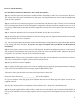
Back View (Battery Replacement): A set of three AA batteries should last at least 1-year under normal conditions. When the time comes to replace the batteries follow these steps: Step 1: Making sure the transmitter is OFF - flip the unit over and remove the battery door. Slide to remove battery door Step 2: Remove the old batteries and dispose of properly.
Transmitter Install Summary: (See Installation Instruction Manual for more detail descriptions) Step 1: Locate the Alliance Razor Display cabinets on the sales floor. Step 2: Using the cabinet keys open POSITION 1 of the cabinet module (a cabinet module consists of a 2 x 2 assembly). 1 2 3 4 Cabinet Positions Step 3: Slide the POWER switch to the ON position as they are being installed in to the cabinets. Do not turn transmitter module power on if there will be any delay in installation.
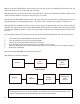
Transmitter Specifications: Message Playback: Power Supply: Size: Color: Shipping Weight: Triggered or Delay (via 433Mhz built-in transmitter) 4.5V (AA x 3) 4.15” x 3.45” x 1.00” (H x W x D) Gray 6 oz. Transmitter Cable Harness Diagram: The Transmitter Module has eight monitored inputs. Four of the inputs are monitored on CH1 (Channel 1) for instant triggering, the other four inputs are monitored on CH2 (Channel 2) for delay triggering.
Message Select Chart: Use the chart below to set the message number to be triggered for an alert condition on the transmitter. Looking at the transmitter ON is to the LEFT, OFF is to the RIGHT.
35 36 37 38 39 40 41 42 43 44 45 46 47 48 49 50 51 52 53 54 55 56 57 58 59 60 61 62 63 64 65 66 67 68 69 70 71 72 73 74 ON OFF ON OFF ON OFF ON OFF ON OFF ON OFF ON OFF ON OFF ON OFF ON OFF ON OFF ON OFF ON OFF ON OFF ON OFF ON OFF ON OFF ON OFF ON OFF ON OFF ON OFF OFF ON ON OFF OFF ON ON OFF OFF ON ON OFF OFF ON ON OFF OFF ON ON OFF OFF ON ON OFF OFF ON ON OFF OFF ON ON OFF OFF ON ON OFF OFF ON OFF ON ON ON ON OFF OFF OFF OFF ON ON ON ON OFF OFF OFF OFF ON ON ON ON OFF OFF OFF OFF ON ON ON ON OFF OFF O
75 76 77 78 79 80 81 82 83 84 85 86 87 88 89 90 91 92 93 94 95 96 97 98 99 100 101 102 103 104 105 106 107 108 109 110 111 112 113 114 20 ON OFF ON OFF ON OFF ON OFF ON OFF ON OFF ON OFF ON OFF ON OFF ON OFF ON OFF ON OFF ON OFF ON OFF ON OFF ON OFF ON OFF ON OFF ON OFF ON OFF ON OFF OFF ON ON OFF OFF ON ON OFF OFF ON ON OFF OFF ON ON OFF OFF ON ON OFF OFF ON ON OFF OFF ON ON OFF OFF ON ON OFF OFF ON ON OFF OFF ON OFF ON ON ON ON OFF OFF OFF OFF ON ON ON ON OFF OFF OFF OFF ON ON ON ON OFF OFF OFF OFF ON
115 116 117 118 119 120 121 122 123 124 125 126 127 128 129 130 131 132 133 134 135 136 137 138 139 140 141 142 143 144 145 146 147 148 149 150 151 152 153 154 ON OFF ON OFF ON OFF ON OFF ON OFF ON OFF ON OFF ON OFF ON OFF ON OFF ON OFF ON OFF ON OFF ON OFF ON OFF ON OFF ON OFF ON OFF ON OFF ON OFF ON OFF OFF ON ON OFF OFF ON ON OFF OFF ON ON OFF OFF ON ON OFF OFF ON ON OFF OFF ON ON OFF OFF ON ON OFF OFF ON ON OFF OFF ON ON OFF OFF ON OFF ON ON ON ON OFF OFF OFF OFF ON ON ON ON OFF OFF OFF OFF ON ON ON
155 156 157 158 159 160 161 162 163 164 165 166 167 168 169 170 171 172 173 174 175 176 177 178 179 180 181 182 183 184 185 186 187 188 189 190 191 192 193 194 22 ON OFF ON OFF ON OFF ON OFF ON OFF ON OFF ON OFF ON OFF ON OFF ON OFF ON OFF ON OFF ON OFF ON OFF ON OFF ON OFF ON OFF ON OFF ON OFF ON OFF ON OFF OFF ON ON OFF OFF ON ON OFF OFF ON ON OFF OFF ON ON OFF OFF ON ON OFF OFF ON ON OFF OFF ON ON OFF OFF ON ON OFF OFF ON ON OFF OFF ON OFF ON ON ON ON OFF OFF OFF OFF ON ON ON ON OFF OFF OFF OFF ON ON
195 196 197 198 199 200 201 202 203 204 205 206 207 208 209 210 211 212 213 214 215 216 217 218 219 220 221 222 223 224 225 226 227 228 229 230 231 232 233 234 ON OFF ON OFF ON OFF ON OFF ON OFF ON OFF ON OFF ON OFF ON OFF ON OFF ON OFF ON OFF ON OFF ON OFF ON OFF ON OFF ON OFF ON OFF ON OFF ON OFF ON OFF OFF ON ON OFF OFF ON ON OFF OFF ON ON OFF OFF ON ON OFF OFF ON ON OFF OFF ON ON OFF OFF ON ON OFF OFF ON ON OFF OFF ON ON OFF OFF ON OFF ON ON ON ON OFF OFF OFF OFF ON ON ON ON OFF OFF OFF OFF ON ON ON
235 236 237 238 239 240 241 242 243 244 245 246 247 248 249 250 251 252 253 254 255 24 ON OFF ON OFF ON OFF ON OFF ON OFF ON OFF ON OFF ON OFF ON OFF ON OFF ON ON OFF OFF ON ON OFF OFF ON ON OFF OFF ON ON OFF OFF ON ON OFF OFF ON ON OFF ON ON ON ON OFF OFF OFF OFF ON ON ON ON OFF OFF OFF OFF ON ON ON ON ON ON ON ON ON OFF OFF OFF OFF OFF OFF OFF OFF ON ON ON ON ON ON ON ON OFF OFF OFF OFF OFF ON ON ON ON ON ON ON ON ON ON ON ON ON ON ON ON ON ON ON ON ON ON ON ON ON ON ON ON ON ON ON ON ON ON ON ON O
Limited Warranty TERMS: Alliance warrants to the original purchaser (“Buyer”) that the Product sold is free from defects in material and workmanship at the time of purchase. The warranty period begins at the time of Product’s original purchase by the first end-user. The warranty applies for one (1) year from the original date of purchase, or as long as the product is owned by the original purchaser, whichever comes first. Included in the warranty are parts and labor.
Designed, Developed and Manufactured in the USA Copyright © 2006, by Alliance • All rights reserved • Revision A - 10/06