
Installation Instructions


19
Nefit BaseLine HRC • 6 720 800 258 (2013/12)
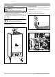
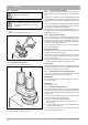
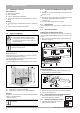
Installatie 5
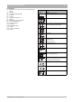
Weerstand per component [Pa] (op basis van M&G / Burgerhout materialen
1)
)
1) Bij gebruik van universeel rookgasafvoermateriaal volgens Gastec Qa, bovenstaande weerstanden per component met factor 1,3 vermenigvuldigen
Component Diameter [mm]
Nefit BaseLine HRC
24/CW3 24/CW4
Maximaal toegestane weerstand p
w
max. [Pa] 80 80
Parallel systeem: luchttoevoerleiding (LTV)
45° bocht
k
Ø80 0,8 0,8
90° bocht
l
Ø80 2,7 2,7
1 m. buis
j
Ø80 0,7 0,7
Parallel systeem: rookgasafvoerleiding (RGA)
45° bocht
k
Ø80 1,1 1,1
90° bocht
l
Ø80 3,9 3,9
1 m. buis
j
Ø80 1,0 1,0
Concentrisch systeem: luchttoevoer-/ rookgasafvoerleiding
45° bocht
n
Ø60/100 8,7 8,7
90° bocht
o
Ø60/100 10,0 10,0
1 m. buis
m
Ø60/100 7,2 7,2
Doorvoerset
Concentrisch systeem: dakdoorvoer
s
Ø80/125 11,5 11,5
Ø60/100 31,2 31,2
Parallel systeem:
dakdoorvoer met broekstuk
Ø80/125 16,3 16,3
Concentrisch systeem:
muurdoorvoer zonder broekstuk
r
Ø80/125 7,8 7,8
Ø60/100 21,3 21,3
Parallel systeem:
muurdoorvoer met broekstuk
Ø80/125 15,5 15,5
Tabel 7 Weerstand per component [Pa]
Neem contact op met de fabrikant van het rookgasafvoermateriaal voor uitgebreide technische informatie en specifieke montagevoor-
schriften.
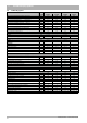
Drukvallen flexibele afvoeren
BaseLine HRC 24/CW3 BaseLine HRC 24/CW4
max. 80 Pa max. 80 Pa
Fabrikant Materiaal
Type Ø
[mm]
Weerstand
[Pa/m]
Aan-
sluitmof [Pa]
Weerstand
[Pa/m]
Aan-
sluitmof [Pa]
M & G PP BM miniflex DN 60 53/63 13,0 26,0 13,0 26,0
Flex 80 81/101 1,9 2,8 1,9 2,8
Panflex RVS INOX DL 50 50/54 9,8 25,0 9,8 25,0
INOX VS 60 60/64 5,7 15,0 5,7 15,0
Ubbink PP Rolux T120 flex 50 50/58 20,0 30,0 20,0 30,0
Tabel 8 Drukvallen flexibele afvoeren