
Installation Instruction
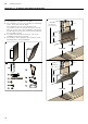
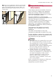
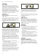
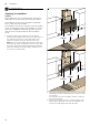
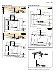
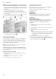
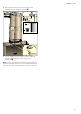
Table Of Contents
- Ú Table of contents
- [en] Instructions for installation and use
- ( Important safety information
- 7 Environmental protection
- Ç Operating modes
- 1 Operating the appliance
- Operating the appliance
- Note:
- Control panel model 1
- Setting the fan
- Noise reduction function
- AirFresh function
- Intensive setting
- Intermediate position for the glass front
- Fan run-on time
- Lighting
- Saturation display
- Audible signal
- Control panel model 2
- Setting the fan
- Noise reduction function
- AirFresh function
- Fan run-on time
- Intensive setting
- Intermediate position for the glass front
- AmbientLight
- 2. Touch the k symbol.
- 3. Within this 10-second period, touch the A or @ symbol until the colour you require is selected.
- Lighting
- Saturation display
- Audible signal
- Control panel model 3
- Setting the fan
- Noise reduction function
- AirFresh function
- Intensive setting
- Intermediate position for the glass front
- Fan run-on time
- Lighting
- Saturation display
- Audible signal
- Control panel variant 4
- Setting the fan
- Noise reduction function
- AirFresh function
- Fan run-on time
- Intensive setting
- Intermediate position for the glass front
- AmbientLight
- 2. Touch the k symbol.
- 3. Within this 10-second period, touch the A or @ symbol until the colour you require is selected.
- 2. Touch the ‘ symbol.
- 2. The sensor controller setting can be changed by touching the @ or A symbol.
- 3. Take your finger off the ‘ symbol.
- 2 Cleaning and maintenance
- Cleaning and maintenance
- : Warning
- : Warning
- : Warning
- : Warning
- : Warning
- : Warning
- : Warning
- 3 Trouble shooting
- 4 Customer service
- ( Important safety information
- K General information
- 5 Installation
- Installation
- Preparing for installation
- 2. Place the template against the line drawn on the wall and fasten it in place. Mark where the screws should be inserted.
- 3. Drill 8 mm diameter holes to a depth of 80 mm for fastening the appliance, remove the template and press in the wall plugs flush with the wall.
- 2. When mounting the appliance, ensure that it engages properly with the mounting supports.
- 3. If required, the appliance can be moved to the right or to the left.
- 4. Firmly tighten the screws for the mounting supports. Hold the bracket firmly when doing so. ¨
- 5. If no duct is to be fitted, screw in the two locking screws without the bracket. ©
- 2. Attach the exhaust air pipe to the reducing connector.
- 3. Use suitable means to seal both joints.
- : Warning
- : Warning
- Risk of electric shock!
- 2. Remove the pieces of protective film from both flue duct sections.
- 3. Push one flue duct section into the other.
- 4. Place flue ducts sections on the appliance.
- 5. Slide the inner flue duct section upwards, attach it to the left and right sides of the retaining bracket, and then slide it down to engage it. ¨
- 6. Screw the flue duct section to the sides of the retaining bracket using two screws. ©
- 7. Clip the lower flue duct section in at the retaining bracket. The connection cable must not be damaged. ª

en Installation
26
Wall-mounting the appliance and levelling it
1. First remove the protective film from the back of the
appliance and, following installation, remove the rest
of the film.
2. When mounting the appliance, ensure that it
engages properly with the mounting supports.
3. If required, the appliance can be moved to the right
or to the left.
4. Firmly tighten the screws for the mounting supports.
Hold the bracket firmly when doing so. ¨
5. If no duct is to be fitted, screw in the two locking
screws without the bracket. ©
Connecting the pipes
If the extractor hood is to be operated in exhaust-air
mode, the pipes must be connected. If the extractor
hood is to be operated in air-recirculation mode, an
optional accessory must be fitted. To do this, refer to
the installation instructions provided.
Note: If an aluminium pipe is being used, smooth the
connection area beforehand.
Exhaust air pipe, dia. 150 mm (recommended size)
Fit the exhaust air pipe directly to the air-pipe connector
and seal the joint.
Exhaust air pipe, dia. 120 mm
1. Fit the reducing connector directly to the air-pipe
connector.
2. Attach the exhaust air pipe to the reducing
connector.
3. Use suitable means to seal both joints.
Attaching the flue duct
If the extractor hood is to be operated in exhaust-air
mode, a flue duct must be fitted.
The flue duct does not need to be fitted for air-
recirculation mode.
:Warning
Risk of injury!
From sharp edges during installation. Always wear
protective gloves while installing the appliance.
:Warning
Risk of electric shock!
Components inside the appliance may have sharp
edges. These may damage the connecting cable. Do
not kink or pinch the connecting cable during
installation.
1. Separate the flue duct sections by removing the
adhesive tape.
2. Remove the pieces of protective film from both flue
duct sections.
3. Push one flue duct section into the other.
Notes
– To prevent scratches, lay paper over the edges of
the outer flue duct section to protect the surface.
– The slots of the inner flue duct section point
downwards.
4. Place flue ducts sections on the appliance.
5. Slide the inner flue duct section upwards, attach it to
the left and right sides of the retaining bracket, and
then slide it down to engage it. ¨