
Installation Instruction
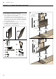
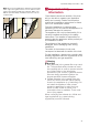
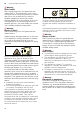
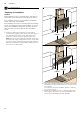
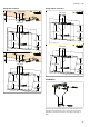
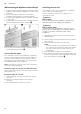
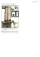
Table Of Contents
- Ú Table of contents
- [en] Instructions for installation and use
- ( Important safety information
- 7 Environmental protection
- Ç Operating modes
- 1 Operating the appliance
- Operating the appliance
- Note:
- Control panel model 1
- Setting the fan
- Noise reduction function
- AirFresh function
- Intensive setting
- Intermediate position for the glass front
- Fan run-on time
- Lighting
- Saturation display
- Audible signal
- Control panel model 2
- Setting the fan
- Noise reduction function
- AirFresh function
- Fan run-on time
- Intensive setting
- Intermediate position for the glass front
- AmbientLight
- 2. Touch the k symbol.
- 3. Within this 10-second period, touch the A or @ symbol until the colour you require is selected.
- Lighting
- Saturation display
- Audible signal
- Control panel model 3
- Setting the fan
- Noise reduction function
- AirFresh function
- Intensive setting
- Intermediate position for the glass front
- Fan run-on time
- Lighting
- Saturation display
- Audible signal
- Control panel variant 4
- Setting the fan
- Noise reduction function
- AirFresh function
- Fan run-on time
- Intensive setting
- Intermediate position for the glass front
- AmbientLight
- 2. Touch the k symbol.
- 3. Within this 10-second period, touch the A or @ symbol until the colour you require is selected.
- 2. Touch the ‘ symbol.
- 2. The sensor controller setting can be changed by touching the @ or A symbol.
- 3. Take your finger off the ‘ symbol.
- 2 Cleaning and maintenance
- Cleaning and maintenance
- : Warning
- : Warning
- : Warning
- : Warning
- : Warning
- : Warning
- : Warning
- 3 Trouble shooting
- 4 Customer service
- ( Important safety information
- K General information
- 5 Installation
- Installation
- Preparing for installation
- 2. Place the template against the line drawn on the wall and fasten it in place. Mark where the screws should be inserted.
- 3. Drill 8 mm diameter holes to a depth of 80 mm for fastening the appliance, remove the template and press in the wall plugs flush with the wall.
- 2. When mounting the appliance, ensure that it engages properly with the mounting supports.
- 3. If required, the appliance can be moved to the right or to the left.
- 4. Firmly tighten the screws for the mounting supports. Hold the bracket firmly when doing so. ¨
- 5. If no duct is to be fitted, screw in the two locking screws without the bracket. ©
- 2. Attach the exhaust air pipe to the reducing connector.
- 3. Use suitable means to seal both joints.
- : Warning
- : Warning
- Risk of electric shock!
- 2. Remove the pieces of protective film from both flue duct sections.
- 3. Push one flue duct section into the other.
- 4. Place flue ducts sections on the appliance.
- 5. Slide the inner flue duct section upwards, attach it to the left and right sides of the retaining bracket, and then slide it down to engage it. ¨
- 6. Screw the flue duct section to the sides of the retaining bracket using two screws. ©
- 7. Clip the lower flue duct section in at the retaining bracket. The connection cable must not be damaged. ª

Important safety information en
21
Note: We recommend fitting the appliance such that the
lower edge of the glass screen is in line with the lower
edges of the adjacent wall-hung cabinets. Make sure
that the specified safety clearances from the hob are
complied with.
(Important safety
information
Impor t ant saf et y informat i on
Read these instructions carefully. Only then
will you be able to operate your appliance
safely and correctly. Retain the instruction
manual and installation instructions for future
use or for subsequent owners.
Check the appliance for damage after
unpacking it. Do not connect the appliance if it
has been damaged in transport.
The appliance can only be used safely if it is
correctly installed according to the safety
instructions. The installer is responsible for
ensuring that the appliance works perfectly at
its installation location.
The surfaces of the appliance are easily
damaged. Avoid damaging them during
installation.
The width of the extractor hood must
correspond at least with the width of the hob.
For the installation, observe the currently valid
building regulations and the regulations of the
local electricity and gas suppliers.
:Warning
Risk of fire!
■ Fatty deposits in the grease filter may catch
fire. The specified safety clearances must
be complied with in order to prevent a build-
up of heat. Refer to the information
provided for your cooker. If gas and electric
hobs are being operated together, the
largest specified clearance applies.
Risk of fire!
■ Grease deposits in the grease filter may
catch fire. Never work with naked flames
close to the appliance (e.g. flambéing). Do
not install the appliance near a heat-
producing appliance for solid fuel (e.g.
wood or coal) unless a closed, non-
removable cover is available. There must
be no flying sparks.
When conveying the exhaust air, official and
legal regulations (e.g. state building
regulations) must be followed.
A B