
Installation Instruction
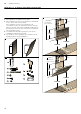


Table Of Contents
- Ú Table of contents
- [en] Instructions for installation and use
- ( Important safety information
- 7 Environmental protection
- Ç Operating modes
- 1 Operating the appliance
- Operating the appliance
- Note:
- Control panel model 1
- Setting the fan
- Noise reduction function
- AirFresh function
- Intensive setting
- Intermediate position for the glass front
- Fan run-on time
- Lighting
- Saturation display
- Audible signal
- Control panel model 2
- Setting the fan
- Noise reduction function
- AirFresh function
- Fan run-on time
- Intensive setting
- Intermediate position for the glass front
- AmbientLight
- 2. Touch the k symbol.
- 3. Within this 10-second period, touch the A or @ symbol until the colour you require is selected.
- Lighting
- Saturation display
- Audible signal
- Control panel model 3
- Setting the fan
- Noise reduction function
- AirFresh function
- Intensive setting
- Intermediate position for the glass front
- Fan run-on time
- Lighting
- Saturation display
- Audible signal
- Control panel variant 4
- Setting the fan
- Noise reduction function
- AirFresh function
- Fan run-on time
- Intensive setting
- Intermediate position for the glass front
- AmbientLight
- 2. Touch the k symbol.
- 3. Within this 10-second period, touch the A or @ symbol until the colour you require is selected.
- 2. Touch the ‘ symbol.
- 2. The sensor controller setting can be changed by touching the @ or A symbol.
- 3. Take your finger off the ‘ symbol.
- 2 Cleaning and maintenance
- Cleaning and maintenance
- : Warning
- : Warning
- : Warning
- : Warning
- : Warning
- : Warning
- : Warning
- 3 Trouble shooting
- 4 Customer service
- ( Important safety information
- K General information
- 5 Installation
- Installation
- Preparing for installation
- 2. Place the template against the line drawn on the wall and fasten it in place. Mark where the screws should be inserted.
- 3. Drill 8 mm diameter holes to a depth of 80 mm for fastening the appliance, remove the template and press in the wall plugs flush with the wall.
- 2. When mounting the appliance, ensure that it engages properly with the mounting supports.
- 3. If required, the appliance can be moved to the right or to the left.
- 4. Firmly tighten the screws for the mounting supports. Hold the bracket firmly when doing so. ¨
- 5. If no duct is to be fitted, screw in the two locking screws without the bracket. ©
- 2. Attach the exhaust air pipe to the reducing connector.
- 3. Use suitable means to seal both joints.
- : Warning
- : Warning
- Risk of electric shock!
- 2. Remove the pieces of protective film from both flue duct sections.
- 3. Push one flue duct section into the other.
- 4. Place flue ducts sections on the appliance.
- 5. Slide the inner flue duct section upwards, attach it to the left and right sides of the retaining bracket, and then slide it down to engage it. ¨
- 6. Screw the flue duct section to the sides of the retaining bracket using two screws. ©
- 7. Clip the lower flue duct section in at the retaining bracket. The connection cable must not be damaged. ª

en Installation
24
5Installation
Instal l ati on
Preparing for installation
Caution!
Ensure that there are no electrical wires, gas pipes or
water pipes in the area where holes are to be drilled.
If the extractor hood is to be operated in exhaust-air
mode, a flue duct must be fitted.
If the extractor hood is to be operated in air-recirculation
mode, an optional accessory must be fitted. To do this,
refer to the installation instructions provided. The flue
duct does not need to be fitted for air-recirculation
mode.
1. Determine where the extractor hood should be
positioned and lightly mark where the lower edge of
the appliance should be on the wall. Determine
where the middle should be based on the hob.
Note: We recommend fitting the extractor hood such
that the lower edge of the glass screen is in line with
the lower edges of the adjacent wall-hung cabinets.
Make sure that the specified safety clearances from
the hob are complied with.
2. Place the template against the line drawn on the wall
and fasten it in place. Mark where the screws should
be inserted.
To fit the flue duct, the template must be cut along
the marked cut line.
3. Drill 8 mm diameter holes to a depth of 80 mm for
fastening the appliance, remove the template and
press in the wall plugs flush with the wall.
$
%
]
]
[
PP
[
PP
[
PP
[
PP
\
\