
Installation Instruction
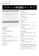
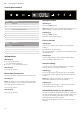
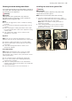
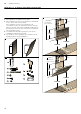
Table Of Contents
- Ú Table of contents
- [en] Instructions for installation and use
- ( Important safety information
- 7 Environmental protection
- Ç Operating modes
- 1 Operating the appliance
- Operating the appliance
- Note:
- Control panel model 1
- Setting the fan
- Noise reduction function
- AirFresh function
- Intensive setting
- Intermediate position for the glass front
- Fan run-on time
- Lighting
- Saturation display
- Audible signal
- Control panel model 2
- Setting the fan
- Noise reduction function
- AirFresh function
- Fan run-on time
- Intensive setting
- Intermediate position for the glass front
- AmbientLight
- 2. Touch the k symbol.
- 3. Within this 10-second period, touch the A or @ symbol until the colour you require is selected.
- Lighting
- Saturation display
- Audible signal
- Control panel model 3
- Setting the fan
- Noise reduction function
- AirFresh function
- Intensive setting
- Intermediate position for the glass front
- Fan run-on time
- Lighting
- Saturation display
- Audible signal
- Control panel variant 4
- Setting the fan
- Noise reduction function
- AirFresh function
- Fan run-on time
- Intensive setting
- Intermediate position for the glass front
- AmbientLight
- 2. Touch the k symbol.
- 3. Within this 10-second period, touch the A or @ symbol until the colour you require is selected.
- 2. Touch the ‘ symbol.
- 2. The sensor controller setting can be changed by touching the @ or A symbol.
- 3. Take your finger off the ‘ symbol.
- 2 Cleaning and maintenance
- Cleaning and maintenance
- : Warning
- : Warning
- : Warning
- : Warning
- : Warning
- : Warning
- : Warning
- 3 Trouble shooting
- 4 Customer service
- ( Important safety information
- K General information
- 5 Installation
- Installation
- Preparing for installation
- 2. Place the template against the line drawn on the wall and fasten it in place. Mark where the screws should be inserted.
- 3. Drill 8 mm diameter holes to a depth of 80 mm for fastening the appliance, remove the template and press in the wall plugs flush with the wall.
- 2. When mounting the appliance, ensure that it engages properly with the mounting supports.
- 3. If required, the appliance can be moved to the right or to the left.
- 4. Firmly tighten the screws for the mounting supports. Hold the bracket firmly when doing so. ¨
- 5. If no duct is to be fitted, screw in the two locking screws without the bracket. ©
- 2. Attach the exhaust air pipe to the reducing connector.
- 3. Use suitable means to seal both joints.
- : Warning
- : Warning
- Risk of electric shock!
- 2. Remove the pieces of protective film from both flue duct sections.
- 3. Push one flue duct section into the other.
- 4. Place flue ducts sections on the appliance.
- 5. Slide the inner flue duct section upwards, attach it to the left and right sides of the retaining bracket, and then slide it down to engage it. ¨
- 6. Screw the flue duct section to the sides of the retaining bracket using two screws. ©
- 7. Clip the lower flue duct section in at the retaining bracket. The connection cable must not be damaged. ª

en Trouble shooting
18
3Trouble shooting
Tr oubl e shoot i ng
Malfunctions often have simple explanations. Please
read the following notes before calling the after-sales
service.
:Warning
Risk of electric shock!
Incorrect repairs are dangerous. Repairs may only be
carried out and damaged power cables replaced by
one of our trained after-sales technicians. If the
appliance is defective, unplug the appliance from the
mains or switch off the circuit breaker in the fuse box.
Contact the after-sales service.
Malfunction table
--------
LED lights
Defective LED lights may be replaced by the
manufacturer, their customer service or a qualified
technician (electrician) only.
:Warning
Risk of injury!
The light emitted by LED lights is very dazzling, and can
damage the eyes (risk group 1). Do not look directly
into the switched on LED lights for longer than 100
seconds.
4Customer service
Cu s t o mer ser vi ce
When calling us, please quote the product number (E
no.) and the production number (FD no.) so that we can
provide you with the correct advice. These numbers can
be found on the rating plate on the top of the appliance.
You can make a note of the numbers of your appliance
and the telephone number of the after-sales service in
the space below to save time should it be required.
Please be aware that a visit by an after-sales engineer
will be charged if a problem turns out to be the result of
operator error, even during the warranty period.
Please find the contact data of all countries in the
enclosed customer service list.
To book an engineer visit and product advice
Rely on the professionalism of the manufacturer. You
can therefore be sure that the repair is carried out by
trained service technicians who carry original spare
parts for your appliances.
Problem Possible cause Solution
The appliance
does not work
The plug is not
plugged in.
Connect the appliance to the
electricity supply
Power cut Check whether other kitchen
appliances are working
Faulty fuse Check in the fuse box to make
sure that the fuse for the
appliance is OK
The lighting does
not work.
The LED lights
are defective.
Call the after-sales service.
The button illumi-
nation does not
work.
The control unit is
faulty.
Call the aftersales service.
E no. FD no.
After-sales serviceO
GB 0344 892 8989
Calls charged at local or mobile rate.
IE 01450 2655
0.03 € per minute at peak. Off peak 0.0088 €
per minute.
Z-Nr:FD:E-Nr:
Type: