TRANSIT Ultimate installation guide 2020-05-13 | v5.08 | Doc. no. 5481104 www.nedapidentification.
TRANSIT Ultimate | installation guide Contents 1 2 3 4 Introduction ........................................................................................................................................................................ 4 1.1 Product description.................................................................................................................................................. 4 1.2 Ultimate features .......................................................................
TRANSIT Ultimate | installation guide 4.5.1 Proximity antenna ............................................................................................................................................. 26 4.5.2 Nedap antenna modulation .............................................................................................................................. 27 5 Firmware update ........................................................................................................................
TRANSIT Ultimate | installation guide 1 Introduction 1.1 Product description The TRANSIT Ultimate is a long-range reader, based on semi active RFID technology, which enables automatic vehicle identification at distances of up to 10 meters (33 ft.) and speeds of up to 200 km/h (125 mph). Key features • Robust industrial design • Read range up to 10 meters [33 ft.
TRANSIT Ultimate | installation guide 1.2 Ultimate features Encrypted tag authentication The TRANSIT Ultimate enables encrypted tag authentication for the Ultimate tags: Smartcard Booster Ultimate, LEGIC Booster Ultimate and Window Tag Ultimate. The authentication uses encryption based upon AES 128-bit keys. Key diversification is used to ensure that a unique encryption key is used for every tag. Implementation The Ultimate-mode features are implemented in the TAB board.
TRANSIT Ultimate | installation guide 2 Installation 2.1 Safety precautions The following safety precautions should be observed during normal use, service and repair: • The TRANSIT Ultimate shall be connected to safety ground. • Disconnecting from (mains) power supply before removing any parts. • The TRANSIT Ultimate shall only be installed and serviced by qualified service personnel. • To be sure of safety, do not modify or add anything other than mentioned in this manual or indicated by NEDAP. 2.
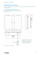
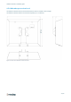
TRANSIT Ultimate | installation guide 2.3 Mounting instructions See the following chapters for details about the dimensions of the reader and the mounting brackets and the locations of the mounting positions. 2.3.1 TRANSIT Ultimate dimensions The picture below shows the dimensions of the TRANSIT Ultimate. All dimensions are in mm. To guarantee water tightness in all positions, the cover screws and the cable glands have to be tightened according our recommendations.
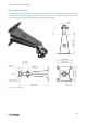
TRANSIT Ultimate | installation guide 2.3.2 Wall mounting The Wall Mounting Set is supplied with the TRANSIT Ultimate reader. When the Wall Mounting Set is assembled mount it to the wall (or to the Pole Mounting Set) based on the dimensions in Figure 3. The TRANSIT Ultimate can be “aimed” with the Wall Mounting Set and when the bolts are tightened, it will stay in place.
TRANSIT Ultimate | installation guide 2.3.3 Pole mounting The TRANSIT Ultimate can be mounted to round poles with maximum diameter of 190 mm and square poles with maximum diameter of 150 mm using the Pole Mounting Kit. The Pole Mounting Kit has to be ordered separately (art. no. 5626595). The Wall Mounting Set will be mounted onto the Pole Mounting Kit.
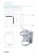
TRANSIT Ultimate | installation guide 2.3.4 Weather protection hood The Weather Protection hood is recommended when the reader is installed in direct sunlight. 287 mm The Weather Protection Hood has to be ordered separately (art. no. 9218327).
TRANSIT Ultimate | installation guide 2.4 Installing the security key pack The optional Security Key Pack (SAM) has to be ordered separately (art. no. 9216537) and is required for the TRANSIT Ultimate to perform the encrypted authentication on the Ultimate tags. Please follow the procedure below to install the Security Key Pack into the TRANSIT Ultimate. Security Key Pack installation procedure Insert the Security Key Pack (SAM) into the TAB board. 1.
TRANSIT Ultimate | installation guide 2.5 Installing a communication board The TRANSIT Ultimate features an on-board USB port and a Wiegand / Magstripe / Barcode interface. See chapter 4.3 for more details. Other communication interfaces can modularly be installed in the reader by means of a communication interface board. There are various communication interface boards available for the TRANSIT Ultimate. See appendix C for available boards and their part numbers.
TRANSIT Ultimate | installation guide 3 OSDP Interface Board For supporting OSDP on the TRANSIT Ultimate it is required to use the OSDP Interface Board, which includes the PCC485/OSDP converter. This board implements the OSDP protocol according to the SIA OSDP v2.1.7 standard, including the Secure Channel Protocol. You may purchase the TRANSIT Ultimate together with the OSDP Installation Board. This is convenient, because then the board is already installed by Nedap. See appendix C for part numbers.
TRANSIT Ultimate | installation guide 3.2 RS485-OSDP wiring The RS485-OSDP wiring should be connected to the RS485 connections on the OSDP Installation Board (OSDP-IB) or directly to the PCC485. See wiring picture below. For point-to-point communication enable the termination resistor. PCC485 switch 1 to ON position. See picture below.
TRANSIT Ultimate | installation guide 3.3 TRANSIT configuration This chapter describes how to configure the TRANSIT Ultimate reader for OSDP installations. TRANSIT firmware requirements The OSDP Interface Board / PCC485 requires to use one of the standard TRANSIT firmware versions, since these support the manual LED and relay control function. • P80 v3.00 • P81 v3.35 • P82 v3.08 • P83 v3.04 • P84 v3.06 • P85 v3.
TRANSIT Ultimate | installation guide 4 Connections 4.1 Overview Power supply See chapter 4.2 Communication See chapter 4.3 Read-disable input See chapter 4.4.2 Relay output See chapter 4.4.1 General purpose inputs See chapter 4.4.4 Tamper switch See chapter 4.4.3 Proximity antenna See chapter 4.5.1 Antenna modulation See chapter 4.5.
TRANSIT Ultimate | installation guide 4.2 Power supply The TRANSIT Ultimate can be powered by AC mains or by a 24 VDC power supply. 4.2.1 AC mains Connect the Mains load and neutral wires to the connector terminals VAC-L and VAC-N. The earth wire should be connected to the dedicated safety ground connection. Input voltage: 100 – 240 VAC Frequency: 60 – 50 Hz VAC-L VAC-N GROUND Figure 12: AC mains connections 4.2.
TRANSIT Ultimate | installation guide 4.2.3 DC output The DC output can be used to supply power to an additional device installed inside or near the TRANSIT Ultimate. +DC-OUT GND Figure 14: DC output connections DC output ratings Output voltage: 23.4 VDC ± 10% Max. output current: 100 mA.
TRANSIT Ultimate | installation guide 4.3 Communication 4.3.1 USB The TRANSIT Ultimate features an USB interface for service and installation purposes. The USB connector (Type B) is accessible behind the cover. Note 1 While the USB interface is in use, the optional communication interface board is disabled. Note 2: While the USB cable is connected, it is not possible to read HID-PROX cards.
TRANSIT Ultimate | installation guide 4.3.2 Wiegand / Magstripe / Barcode The Wiegand, Magstripe and Barcode interfaces share the same connections. The connections are described below. The actual protocol output depends upon the reader firmware. Please refer to the firmware manual for more details.
TRANSIT Ultimate | installation guide 4.3.3 RS232 An RS232 interface is available when the RS232 or HIB interface board has been installed. TRANSIT SIDE DIN 25 PC SIDE Name DIN 9 Name 2 TXD 2 RXD 3 RXD 3 TXD 7 GND 5 GND Cable specification 3 x 0.25mm2 shielded Maximum cable length 30 meter. 4.3.4 RS422-485 An RS422 or RS485 interface is available when the RS422-485 interface board has been installed. SW1 selects RS422 or RS485. SW2 enables the termination resistor.
TRANSIT Ultimate | installation guide 4.4 Digital I/O 4.4.1 Relay output The relay output is automatically activated upon successful identification / authentication of a transponder. The automatic-relay-activation-mode can be configured using the firmware. Please refer to the firmware manual for more details. Authentication is only performed when Ultimate-mode is enabled. See chapter 6.1 for more details. By default the front cover LED lights-up simultaneously with the relay output.
TRANSIT Ultimate | installation guide 4.4.2 Read disable input The reading of the TRANSIT Ultimate can be stopped with the read disable input (RDIS). This input is commonly used in combination with a sensor (e.g. inductive loop) that detects the presence of a person or vehicle. Use a potential-free contact (relay) to connect the internal 5V to the RDIS input. Leave open or unconnected when reading should be enabled. Connections R-DIS Read disable input 5V Internal 5V source for read disable input.
TRANSIT Ultimate | installation guide 4.4.3 Tamper switch The TRANSIT Ultimate features an internal tamper switch that indicates when the cover is opened. This contact may be connected to an external alarm system. The contacts are normally closed when the cover is in place. Tamper switches of multiple TRANSIT Ultimate readers may be connected in series. Connections TAMPER TAMPER Tamper switch contacts (normally closed) “ Contact ratings Max. switching current: 50 mA (0.5V voltage drop) Max.
TRANSIT Ultimate | installation guide 4.4.4 General purpose inputs Three general purpose inputs are available on the TRANSIT Ultimate. The inputs are active low. No external voltage should be applied to the inputs. Connect to ground using a potential-free contact (relay) to activate. Leave open or unconnected when not used or inactive. Depending upon the used firmware version, these inputs optionally can be used to activate the relay or control the front-cover 3-color LED.
TRANSIT Ultimate | installation guide 4.5 Special connections 4.5.1 Proximity antenna Optionally a NEDAP proximity antenna can be connected to the TRANSIT Ultimate to enable simultaneously long-range and proximity identification. This is useful when controlling a gate where vehicles as well as pedestrians, cyclists and/or motorists can enter. The antenna can be either a NEDAP low-frequency proximity antenna or a NEDAP reader with antenna modulation output (e.g. NVITE or uPASS Access).
TRANSIT Ultimate | installation guide 4.5.2 Nedap antenna modulation The Nedap antenna modulation interface is used to connect the TRANSIT Ultimate to the PCC485 OSDP protocol converter. See chapter 3. Alternatively the Nedap antenna modulation interface can also be used to connect the TRANSIT Ultimate to NEDAP AEOS access control hardware such as the AP1001. Connections MHF+ Antenna modulation output, connect to PCC485 HF+ or (AP1001 ANT).
TRANSIT Ultimate | installation guide 5 Firmware update The TRANSIT Ultimate supports the same firmware versions as the TRANSIT Standard. Different firmware versions are available to support different features and communication protocols. For each firmware version a separate manual is available. The firmware can be changed or updated using the TRANSIT Firmware Upgrade software tool. Firmware update procedure • Start TRANSIT Firmware Update (PICLOAD) software. • Select communication port (e.g. COM1).
TRANSIT Ultimate | installation guide 6 Configuration The TRANSIT Ultimate has different dip-switches to select configuration settings. Figure 25 shows the default dip-switch settings and their location. SW2 SW1 SW1 ON 1 2 3 5 4 6 7 8 1 SW3 SW2 ON 2 3 1 4 SW3 ON 2 3 4 Figure 25: Dip-switch locations The switches SW1 are used to select various options within the actual loaded firmware. For example to select the serial baud rate, wiegand output options, etc.
TRANSIT Ultimate | installation guide 6.2 Range beeper Enable or disable the internal range beeper. The beeper indicates transponder identification. The signal strength of the identified transponder determines the beeping frequency. When the transponder is near to the reader the range beeper will beep fast SW2 ON 1 2 3 4 SW3 ON 1 2 3 4 Range beeper ON SW2 ON 1 2 3 4 SW3 ON 1 2 3 4 Range beeper OFF 6.
TRANSIT Ultimate | installation guide 6.4 Frequency select The TRANSIT Ultimate reader operates in the 2.45GHz ISM frequency band. When two or more readers are within a range of 15 meters (50 feet), these readers should be set on a different operating frequency. It may also be required to select a different frequency to avoid disturbance between the TRANSIT Ultimate and other 2.45GHz equipment, such as Wi-Fi access points. Please also read chapter 6.6 when experiencing interference.
TRANSIT Ultimate | installation guide 6.5 Read range control The read range of the TRANSIT Ultimate can be controlled with the embedded squelch function. The squelch references the received signal strength against the squelch level threshold. When the received signal strength is below the squelch threshold level no identification is possible. The received signal strength becomes higher when the transponder comes closer to the reader.
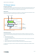
TRANSIT Ultimate | installation guide 6.6 Microwave time-sharing The microwave antenna of the TRANSIT Ultimate is continuously on. This will ensure the fastest identification. However it may cause interference on other 2.45GHz equipment. Enable the microwave time-share mode to only use the selected frequency periodically (the reader automatically switches on and off). During the periods that the TRANSIT reader is off, other equipment can use the same frequency undisturbed.
TRANSIT Ultimate | installation guide 7 LED indications 7.1 Main board LED indications A number of LEDs on the main board of the TRANSIT Ultimate indicate the status of the reader. The list below describes the function of each LED. Read disable LEDs Unlocked Figure 29: LED indications main board Led Description RX_LEVEL LED bar indicating the received tag signal strength. This LED bar also indicates the presence of radio interference. In case of interference, try switching to a different frequency.
TRANSIT Ultimate | installation guide 7.2 TAB board LED indications The LEDs on the TAB board indicate its status. These LEDs are very useful when troubleshooting the Ultimate-mode 2.45 433 GOOD STS ERR Tx Rx features. Below the function of each LED is described. Figure 30: LED indications TAB board Led STS Description TAB board status LED Fast blinking: Boot loader active. Indicated after restart. Regular blinking: Heartbeat (0.5s on / 0.5s off) ERR Special blink 1: Programmer firmware (0.
TRANSIT Ultimate | installation guide A Technical specification Technical specification TRANSIT Ultimate Power supply 100 – 240 VAC (60 – 50 Hz) or 24 VDC (± 10%) Power consumption < 25 VA (AC), < 20 W (DC) Power output 24Vdc, 0.
TRANSIT Ultimate | installation guide B Frequency channels Frequency channel selection table: Display value 4C 4D 4E 4F 50 51 52 53 54 55 56 57 58 59 5A 5B 5C 5D 5E 5F 60 61 62 63 64 65 66 67 68 69 6A 6B 6C 6D 6E 6F 70 71 72 73 74 75 76 77 78 79 7A 7B Frequency (GHz) 2.4360 2.4366 2.4372 2.4378 2.4384 2.4390 2.4396 2.4402 2.4408 2.4414 2.4420 2.4426 2.4432 2.4438 2.4444 2.4450 2.4456 2.4462 2.4468 2.4474 2.4480 2.4486 2.4492 2.4498 2.4504 2.4510 2.4516 2.4522 2.4528 2.4534 2.4540 2.4546 2.4552 2.4558 2.
TRANSIT Ultimate | installation guide C Nedap part numbers Product Part number Description 9215689 TRANSIT Ultimate 9216537 Security Key Pack (SAM) 5626595 Pole Mounting Kit 9218327 Weather Protection Hood 9229078 OSDP Installation Board (includes PCC485) 7819102 HID interface board (HIB) 7817940 TCP/IP interface board 7817347 RS422-485 interface board 7806434 RS232 interface board 9564314 Window Tag Ultimate 9982809 Smartcard Booster Ultimate 9982817 LEGIC Booster Ultimate 38/40
TRANSIT Ultimate | installation guide D FCC / IC statement FCC ID: CGDTRANSITULT2 IC: 1444A-TRANSITULT2 FCC ID: CGDTRANSITULTI IC: 1444A-TRANSITULTI Compliance statements (part 15.19) This device complies with part 15 of the FCC Rules and to RSS210 of Industry Canada. Operation is subject to the following two conditions: (1) this device may not cause harmful interference, and (2) this device must accept any interference received, including interference that may cause undesired operation.
TRANSIT Ultimate | installation guide E Disclaimer This information is furnished for guidance, and with no guarantee as to its accuracy or completeness; its publication conveys no license under any patent or other right, nor does the publisher assume liability for any consequence of its use; specifications and availability of goods mentioned in it are subject to change without notice; it is not to be reproduced in any way, in whole or in part, without the written consent of the publisher.