MultiSync XT5000 High Light Output Projection System User’s Manual
CAUTION: To turn off main power, be sure to remove the plug from power outlet. The power outlet socket should be installed as near to the equipment as possible, and should be easily accessible. Precautions Please read this manual carefully before using your NEC MultiSync XT5000 Projector and keep the manual handy for future reference. 3. GSGV Acoustic Noise Information Ordinance: The sound pressure level is less than 70 dB(A) according to ISO 3744 or ISO 7779. WARNING This is a Class A product.
Fire and Shock Precautions Important Safeguards These safety instructions are to ensure the long life of your projector and to prevent fire and shock. Please read them carefully and heed all warnings. Installation 1. Place the projector on a flat, level surface and in a dry area free from dust and moisture. 2. Do not place the projector in direct sunlight, near heaters or heat radiating appliances. 3. Exposure to direct sunlight, smoke or steam could harm internal components. 4.
Précautions contre l'incendie ou la décharge Recommandations importantes Ces instructions de sécurité ont pour but d'assurer une longue vie à votre projecteur et d'éviter un incendie ou une décharge électrique. Prière de les lire avec attention et de tenir compte de tous les avertissements. Installation 1. Placer le projecteur sur une surface plate et de niveau, et dans un endroit sec et à l'abri des poussières et de l'humidité. 2.
LIMITED WARRANTY (USA and Canada only) NEC Technologies, Inc.(hereafter NECTECH)warrants this product to be free from defects in material and workmanship under the following terms. HOW LONG IS THE WARRANTY Parts and labor are warranted for (1) One Year from the date of the first customer purchase. The lamp is warranted for 1000 hours of operating time or 90 days, whichever comes first. Decrease in lamp light output level is not covered by this warranty.
TABLE OF CONTENTS INTRODUCTION Lamp .................................................................................... E–35 Lamp Mode ................................................................... E–35 Lamp Output ................................................................. E–35 Factory Default .................................................................... E–36 All Data/Current Signal ................................................. E–36 Introduction to the MultiSync XT5000 Projector ..
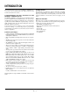
INTRODUCTION This section introduces you to your new MultiSync XT5000 Projector, provides a list of materials that comes with your projector and describes the features and controls. Congratulations On Your Purchase Of The MultiSync XT5000 Projector The MultiSync XT5000 is one of the finest, most technically advanced projectors available today.
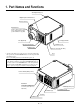
1. Part Names and Functions Stacking Pad (4 pcs) Digital Input Terminal Panel Remote Sensor PC Card Slot Insert a flash memory card here to upgrade the projector system software or copy data Lens (Optional) Carrying Handle Input Terminal Panel Ventilation (out) Ventilation (in) Release Lever (both sides) * To turn on the main power to the projector, press the switch to the ON position (I) and the POWER indicator on the rear panel will turn amber in color.
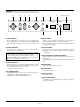
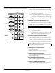
Controls 11 10 9 8 7 5 LENS SHIFT FOCUS ZOOM MENU SELECT ENTER 4 INDICATOR ON - 2 Remote sensor POWER ON/OFF + OFF CANCEL 6 1. Power Button STATUS 3 1 5 Enter Button Press to turn the projector on when the projector is in the standby condition (Main Power switch must be on and the POWER indicator lit amber). Press and hold for 2 seconds to turn off the projector. 2. Power Indicator Executes your menu selection and activates items selected from the menu.
1 INPUT 3 RGB Connector (Mini D-Sub 15 pin) Terminal Panel 5 Connect your PC or other analog RGB equipment such as a highdefinition document camera. 6 2 Option Connector (Mini D-Sub 9 pin) INPUT3 INPUT2 INPUT1 INPUT4 RGB R/Cr R/Cr Cr G/Y G/Y Y B/Cb B/Cb Cb H/HV H/HV For system expansion such as PC-control. IN: connect to the external equipment such as PC. OUT: for daisy-chaining multiple projectors and operating them with the same external equipment.
10 INPUT 8 S-VIDEO 2Terminal (Mini DIN 4 pin) Connect to the S-video output of the external equipment such as a VCR with an S-video output. This terminal allows switching between S2 and S1 VIDEO input modes. See the "S-Video Mode Select" section for more information. Push the left side of the panel to open the compartment for the RGB Digital connectors and the optional SDI board. OUTPUT INPUT9 OUTPUT INPUT 0 RGB DIGITAL SDI 11 Space to install the optional SDI board.
3 MENU Remote Control Press to display the main menu. While pressing and holding CTL, press this button to display the Remote Control ID dialog box to specify the remote control ID. 4 ENTER POWER OFF ON Executes the menu selection and activates items selected from the menu. When the slidebar or dialog box is diplayed: Pressing this button confirms adjustments/setting and returns to the previous menu display.
12 INFO Displays the "Source Information" or "Projector Information" window. This button toggles between these two windows. 26 CTL Used in conjunction with other buttons, similar to a shift key on a computer. 27 Infrared Transmitter 13 TEST Direct the remote control toward the remote sensor on the projector cabinet. Press to display the test pattern. Pressing this button sequentially selects nine test patterns. 14 HELP 28 Remote Jack Provides online help.
2. INSTALLATION This section describes how to install the lens, set up the projector and how to connect video and audio sources. 3) Lift up the lower lens hood by 1 cm to release the hook. Remove the lower lens hood. Optional Lens Installation Four optional lenses are available: TL-08SF, TL-1Z, TL-2Z and TL4Z. Preparation * Turn the projector off, wait for the cooling fan to stop, then turn off the main power switch on the rear panel.
3) Rotate the lens barrel clockwise to fix the lens unit. 2) Insert the upper lens hood while pushing the left and right bottom. Secure the two screws. Lens barrel 3. Secure the fixed screws and connect the extension cable attached to the projector. 1) Secure the three screws on the lens holder. 2) Insert the connector of the lens unit into the socket of the extension cable attached to the projector. NOTE: This completes installation for the optional lens TL-08SF and TL-1Z.
Setting Up The projector Selecting A Location The further your projector is from the screen or wall, the larger the image. The minimum size the image can be projected is 80" (2 m) measured diagonally. The largest the image can be is 500" (12.7 m). To set up and use the projector, you must first do: 1. Determine the screen size and the optional lens to be used. NOTE: Refer to page E-14 for lens installation. 500" 400" 2.
Attaching the Power Cable Stopper The Power cable stopper is provided with the projector so that the cable cannot be accidentally unplugged from the AC IN. 1) Remove two screws. These screws are used later again. OF 2) Plug the power cable into the AC IN and then attach the stopper. Power cable Stopper 3) Fix the stopper using the two screws.
Screen Size and Projection Distance Lens Shift Adjustable Range 1. Place your projector on a flat level surface at the optimal distance from the screen. (Avoid having bright room lighting or sun light directly on the screen or projection surface.) 2. Connect the power cable, remove the lens cap and turn the projector on. (If no input signal is available, the projector will display a black screen.) 3. Ensure that the projector is square to the screen. 4.
Reflecting The Image Top View Normal projection Using a mirror to reflect your projector's image enables you to enjoy a much larger image in a much smaller space. Contact your dealer if you need a mirror. If you're using a mirror and your image is inverted, use the [Main Menu] → [Projector Options] → [Setup] → [Orientation] to select the correct orientation. (See page E-39.
Setting up for Double or Triple Stacking in Link Mode INPUT3 INPUT2 INPUT1 INPUT4 RGB R/Cr R/Cr Cr G/Y G/Y Y B/Cb B/Cb Cb H/HV H/HV V V INPUT3 INPUT2 INPUT1 INPUT4 RGB R/Cr R/Cr Cr G/Y G/Y Y B/Cb B/Cb Cb H/HV H/HV V V INPUT3 INPUT2 INPUT1 INPUT4 RGB R/Cr R/Cr Cr G/Y G/Y Y B/Cb B/Cb Cb H/HV H/HV V V OPTION IN OU OUT TP Master projector UT REMOTE1 OU TP UT INP UT 9 Slave projector OPTION IN INP UT 9 OUT REMOTE1 OUTPUT INPUT9 OUTPUT INPU
3) Adjusting and registering signals to be projected in Link mode and stack application. Signal Data Preparation 3-1. Create data for the master projector and copy data to the slave projectors. 3-1-1. Choose one projector as the master. 3-1-2. Turn the master projector on. 3-1-3. Display all desired input signals, make adjustment to each signal, then save all adjustments on the master projector. (Adjustments will be saved automatically.) 3-1-4. Turn the master projector off (standby mode). 3-1-5.
3. CONNECTIONS When used in standalone operation Connecting Your PC Or Macintosh Computer Connecting Your VCR Or Laser Disc Player Connecting your PC or Macintosh computer to XT5000 Projector will enable you to project your computer's screen image for an impressive presentation. Use common RCA cables (not provided) to connect your VCR or laser disc player to your MultiSync XT5000 Projector. To make these connections, simply: 1. Turn off the power to your projector and VCR or laser disc player. 2.
When Used with One Switcher (ISS-6020/ISS-6020G) Up to 10 input signals can be accepted when the projector is connected to one Switcher. Using the projector with the Switcher allows easy adjustment and signal selection.
When Used with Two or More Switchers (100 Inputs) Up to 100 inputs can be accepted using the NEC ISS-6020 Switcher. How to make connections: 1 2 Connect the REMOTE 1 terminal of the master Switcher to the REMOTE 1 of the projector using the optional control cable (15p15p/CTL-6010). Next connect the REMOTE 2 terminal of the master Switcher to the REMOTE 1 terminal of the first slave Switcher using the same optional control cable as mentioned above.
Set the DIP switch (S8601) of the Switcher as follows: NOTE: Slave numbers 1 to 10 must correspond to the master’s slot numbers 1 to 10.
REMOTE 1 Connector 5 4 3 2 1 10 9 8 7 6 15 14 13 12 11 This connector is used for either connecting the ISS-6020/ISS-6020G Switcher or a third party external control device. When the Switcher is used, connect it with the optional control cable (15-15 pin; 50 ft./16m; CTL-6010) to this connector. When used with the Switcher. Pin No. FUNCTION 1, 2, 6 and 7 Sending and receiving data when the Switcher is used. 9 Identifying the Projector 15 Ground Others Used inside the Projector.
When used in stand alone operation. Pin No.
Operating Multiple Projector with Remote Control You can operate multiple projectors with the same remote control in wireless operation. To do so: 1. Select [Main Menu]→[Projector Options]→[Setup]→[Page 3]→[Projector ID] and assign an ID number to each projector. See also page E-40. 2. On the remote control specify the ID number of the projector to be adjusted. Press and hold the CTL and press MENU (ADDRESS) button to enter the ID number.
4. OPERATION This section describes how to select a computer or video source, adjust the picture and sound, edit a signal and adjust all other settings and adjustments for proper projector set-up. General Controls Before you turn on the projector ensure that the computer or video source is turned on and that the lens cap is removed. 1. Turn On The Projector Plug the supplied power cable into the AC outlet. The main power switch is on the rear panel of the projector.
A List of Direct Key Combinations CTL+ INPUT (1-10) Switches to any selected signal found in the Entry List. To enable this combination, you must first assign specific remote keys for direct input selection in the Entry Edit window. CTL+ ENTER (While displaying Entry list) Displays the Entry Edit Command window. CTL+ MUTE PICTURE(SHUTTER) Blocks all Projector Light Output. CTL+CANCEL Returns to the previous menu without closing the slidebar or dialog.
Menu Tree Menu Source Select Adjustments Image Options Projector Options PC Card Files Help Test Pattern Sub menu RGB 1 RGB 2 RGB 3 Component (YCrCb) Video 1 Video 2 S-Video 1 S-Video 2 more RGB (DIGITAL) SDI Entry List Picture Blanking Image Color Temperature White Balance Switcher more Keystone Ref. White Bal.
Menu Elements Tab Title bar Highlight Solid triangle Cancel Button OK Button Check box Radio button Slide bar Menu windows or dialog box typically have the following elements: Title bar: Indicates the menu title. Highlight: Indicates the selected menu or item. Solid triangle: Indicates further choices are available. A highlighted triangle indicates the item is active. Tab: Indicates a group of features in a dialog box. Selecting any tab brings its page to the front.
* Edit Enables you to change source name or assign the direct key. * The following buttons are not available for the currently projecting signals: 1) The Cut and Paste buttons on the Entry Edit Command screen 2) The Input Terminal button on the Entry Edit screen Menu Descriptions & Functions Source Select Enables you to select a video source such as a VCR, DVD player, laser disc player, computer or document camera depending on what is connected to your inputs.
Image Adjustments The Adjustments Menu provides access to controls for your image. Use the ▲/▼ buttons on your remote control or the projector cabinet to highlight the menu for the item you want to adjust. Auto Adjust: When “Auto Adjust” is set to “On”, the projector automatically determines the best resolution for the current RGB input signal to project an image using NEC’s Advanced AccuBlend Intelligent Pixel Blending Technology.
Video Filter This feature reduces video noise. Select the appropriate filter for your signal. Bar 0 ..................... Off Bar 1/3 .................. High Bar 2/3 .................. Medium Bar full ................. Low Keystone Keystone is the distortion of a projected image that usually creates a wider top than bottom. Aiming a projector upward on a wall rather than straight at a wall creates this distortion. Use the or buttons on the slide bar to correct this keystone (trapezoidal) distortion.
Factory Default VD Delay (Expert mode only): This feature is used to correct vertical jitter of non-standard interlaced signal. Select one of the three VD delay levels. Returns all adjustments and settings to the factory preset level. All Data: Resets all adjustments and settings for all the signals to the factory preset. Including Entry List: Also deletes all the signals in the Entry List and returns to the factory preset.
Noise Reduction Telecine(Expert mode only) Use 3:2 pull down correction to eliminate jitter and artifacts in video. Auto: For film source such as a DVD player Off: For signals other than film sources Signal Level Select one of the following three levels for reducing video noise. Low, Medium or High. NOTE: The lower the Noise Reduction level, the better the image quality. Increasing Noise Reduction lowers video bandwidth. This function is only active when multiple projectors are in use.
On/Off Timer 1. Select your desired time between 30 minutes and 2 hours in 30 minutes. 2. Select Set and press the ENTER button on the remote control. 3. The remaining time starts counting down. 4. The projector will turn off after the countdown is complete. Menu Up to eight settings can be programmed. • Before setting On/Off Timer, make sure that Date, Time Preset feature is set. • Even after setting On/Off Timer, turning the projector on or off with the remote control is possible.
1. Type in date. Enter month, date and year in this order using INPUT buttons on the remote control. Month and date must be entered in two digits. For example, to display "February", press "0" and "2". 2. Type in time. Time is expressed in the 24-hour format. For example, 6:00 p.m. is entered as 18:00. 3. Select "OK" and press ENTER. Closing the window allows the clock to start. S-Video Mode Select: This feature is used to select the S-Video signal detection mode.
User Name: Type in your desired name using the INPUT keys on the remote control. Select one character at a time with the INPUT buttons 1 through 10(0) and by moving the cursor with the CURSOR button. The user name must be 18 characters or less. Only after completely finishing the selection of the characters, press ENTER. Sync Termination (RGB1/2): This functions is used to select the impedance of the sync signal. Select “ 75 Ω” or “Hi-Z”.
Displaying Current Status of Link Mode PC Card Files When selecting the tab "Page 4 ", you will get the following dialog box. Displays a list of all the files stored in the PC card so that you can select a file you want to display. You can also sort files by file name or date, or display the file. Although a list of all the files in the PC card is displayed, you can view files in text, HTML, JPEG and BMP format only. Selecting “Execute” displays the file you selected.
5. Specifications Optical Panel *1 DMDTM .9" x 3 1024 x 768 native resolution up to 1280 x 1024 with advanced AccuBlendTM Technology Lamp 1.
Acceptable Sync Sys Separate Sync/Composite Sync/ Sync on Green Memory 100 individual memory locations Menu System Pull down multilingual on-screen display English/German/French/Italian/Spanish/ Swedish/Japanese Keystone Correction Digital through Advanced AccuBlend Technology Range 0 - ±30˚ RS232C (1) D-sub 9 pin Contact Closure Switcher (2) D-sub 15 pin In/Out Addressable Remote Control (wired / wireless) External Control Power Requirement 100-120 / 200-240 VAC, 50/60Hz Input Current 11 / 7.
6. Optional Accessories Lens TL-08SF (Short Focal Lens 0.84) TL-1Z (Zoom Lens 1.5 - 2.5:1) TL-2Z (Zoom Lens 2.5 - 4.0:1) TL-4Z (Zoom Lens 4.0 - 7.0:1) Cable XT D-CABLE 5M (DFP cable) Interface Board XT SDI BOARD 7. Link Mode: Compatible Input Signal List (Expert mode only) NOTE: Signals other than specified here are not available in the digital link mode. If you want to input them, use a commercially available distribution amplifier to connect the terminals of each projector.
8. List of Menu Items Available on Link Mode (Expert Mode) See the table below for available functions in the digital link mode and the analog link mode. Menu (Expert mode) Source Select Adjustments Image Options Projector Options PC Card Files Help Test Pattern Direct Key Picture (all items) Blanking Image Auto Adjust Position Pixel Adjust Resolution Video Filter Color Temperature White Balance Switcher Keystone Ref.
Appendix 682 (26.85) Dimensions 54 (2.13) 506 (19.92) 35.5 (1.40) 30 (1.18) 308 (12.13) 326 (12.83) 174 (6.85) The drawings do not include the lens part.