Portable Projector VT46 User’s Manual
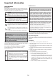
Important Information RF Interference Safety Cautions Precautions WARNING The Federal Communications Commission does not allow any modifications or changes to the unit EXCEPT those specified by NEC Soluctions (America), Inc. in this manual. Failure to comply with this government regulation could void your right to operate this equipment. This equipment has been tested and found to comply with the limits for a Class B digital device, pursuant to Part 15 of the FCC Rules.
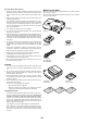
Fire and Shock Precautions What's in the Box? 1. Ensure that there is sufficient ventilation and that vents are unobstructed to prevent the build-up of heat inside your projector. Allow at least 3 inches (10 cm) of space between your projector and a wall. Make sure your box contains everything listed. If any pieces are missing, contact your dealer. Please save the original box and packing materials if you ever need to ship your VT46 Projector. 2.
TABLE OF CONTENTS Important Information ........................................... E-2 MAINTENANCE ................................................... E-25 Safety Cautions ........................................................................................... E-2 What's in the Box? ...................................................................................... E-3 Replacing the Lamp ............................................................................... Cleaning ......................
INTRODUCTION Introduction to the Projector About this user's manual This section introduces you to your new VT46 Projector and describes the features and controls. The fastest way to get started is to take your time and do everything right the first time. Take a few minutes now to review the user's manual. This may save you time later on. At the beginning of each section of the manual you'll find an overview. If the section doesn't apply, you can skip it.
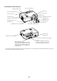
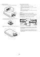
Part Names of the Projector Monaural Speaker (1W) Controls (See page E-7) Zoom Lever Lamp Cover (See page E-25) Focus Ring Lamp Cover Screw Lens Ventilation (outlet) Heated air is exhausted from here Adjustable Tilt Foot Lever (See page E-16) Adjustable Tilt Foot (See page E-16) Adjustable Tilt Foot Lever (See page E-16) Lens Cap Adjustable Tilt Foot (See page E-16) Remote Sensor (See page E-9) Remote Sensor (See page E-9) Ventilation (inlet) / Filter Cover Built-in Security Slot ( Main Power Switc
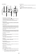
12. ENTER Button Executes your menu selection and activates items selected from the menu. Top Features 5 6 78 10 234 11 13. CANCEL Button Pressing this button will return to the previous menu. While you are in the main menu, pressing this button will close the menu. 9 1 12 13 1. POWER Button (ON / STAND BY)( ) Use this button to turn the power on and off when the main power is supplied and the projector is in standby mode.
Terminal Panel Features 2 Part Names of the Remote Control 1 1 5 2 4 4 3 5 6 7 8 9 3 1. RGB IN / Component Input Connector (Mini D-Sub 15 Pin) Connect your computer or other analog RGB equipment such as IBM compatible or Macintosh computers. Use the supplied RGB cable to connect to your computer. This also serves as a component input connector that allows you to connect a component video output of component equipment such as a DVD player. This connector also supports SCART output signal.
Battery Installation Remote Control Precautions 1. Push the catch to the right and remove the battery holder. • Handle the remote control carefully. • If the remote control gets wet, wipe it dry immediately. • Avoid excessive heat and humidity. 32 20 LT R • If you will not be using the remote control for a long time, remove the battery. O C ELL S JAPAN H Catch 3V • Do not place the battery upside down.
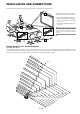
INSTALLATION AND CONNECTIONS This section describes how to set up your projector and how to connect video and audio sources. Your projector is simple to set up and use. But before you get started, you must first: 1 1 Set up a screen and the projector. 2 Connect your computer or video equipment to the projector. See page E-12 – 14. 3 Connect the supplied power cable. See page E-14. 2 NOTE: Ensure that the power cable and any other cables are disconnected before moving the projector.
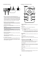
Throw Distance and Screen Size The following shows the proper relative positions of the projector and screen. Refer to the table to determine the position of installation. Distance Chart B = Vertical distance between lens center and screen center C = Throw distance D = Vertical distance between lens center and top of screen (bottom of screen for desktop) α = Throw angle Screen Width Screen Diagonal Screen Height NOTE: Distances may vary +/-5%.
Making Connections NOTE: When using with a notebook PC, be sure to connect between the projector and the notebook PC before turning on the power to the notebook PC. In most cases signal cannot be output from RGB output unless the notebook PC is turned on after connecting with the projector. * If the screen goes blank while using your remote control, it may be the result of the computer's screen-saver or power management software.
Connecting Your DVD Player RGB IN Optional 15-pin-to-RCA (female)⳯3 cable (ADP-CV1) Component video RCA⳯3 cable (not supplied) Audio Equipment DVD player AUDIO IN L R AUDIO OUT L R Component Y Cb Cr Audio cable (not supplied) You can connect your projector to a DVD player with component output or Video output.
Connecting Your VCR or Laser Disc Player VIDEO IN S-VIDEO IN S-Video cable (not supplied) Video cable (not supplied) Audio equipment VCR/ Laser disc player AUDIO IN AUDIO OUT L L R R S-VIDEO OUT Audio cable (not supplied) VIDEO OUT Use common RCA cables (not provided) to connect your VCR, laser disc player or document camera to your projector. To make these connections, simply: 1. Turn off the power to the projector and VCR, laser disc player or document camera.
PROJECTING AN IMAGE (BASIC OPERATION) This section describes how to turn on the projector and to project a picture onto the screen. 2. Press the ENTER button to execute the selection. Turning on the Projector NOTE: • The projector has two power switches: main power switch and POWER (ON/ STAND BY) button. • When plugging in or unplugging the supplied power cable, make sure that the main power switch is pushed to the off (O) position. Failure to do so may cause damage to the projector.
Place your projector on a flat level surface and ensure that the projector is square to the screen. CAUTION Do not use the tilt-foot for purposes other than originally intended. Misuses such as gripping the tilt-foot or hanging on the wall can cause damage to the projector. Lift the front edge of the projector to center the image vertically. * If the projected image does not appear square to the screen then use the Keystone feature for proper adjustment. See page E-21.
Optimizing RGB Picture Automatically Turning off the Image and Sound Adjusting the Image Using Auto Adjust Press the MUTE button on the remote control to turn off the image and sound for a short period of time. Press again to restore the image and sound. Optimizing RGB image automatically Press the AUTO ADJ. button on the projector cabinet to optimize an RGB image automatically.
USING ON-SCREEN MENU 6. Repeat steps 2-5 to adjust an additional item, or press the MENU button to close the menu. Basic Menu Operation Using the Menus NOTE: The on-screen menu may not be displayed correctly while interlaced motion video image is projected. 1. Press the MENU button on the remote control or projector cabinet to display the Menu. 2. Press the SELECT GH buttons on the remote control or the projector cabinet to highlight the menu for the item you want to adjust or set. 3.
List of Menu Items Picture Brightness Contrast Sharpness Color Hue Picture Management Image Keystone Keystone Save Aspect Ratio Cinema Position Setup Language Menu Color Select Menu Display Time Background Orientation Advanced Security Control Panel Key Lock High Speed Fan Mode Signal Select RGB Video S-Video Page2 Information Page1 Page2 Page3 Default Factory Default Presentation, Video, Movie, Graphic, sRGB User Base Setting Presentation, Video, Movie, Graphic, sRGB White Balance Brightness R,G,B Cont
Menu Elements Title Slide bar Radio button Source Highlight Check mark Tab Key symbol Menu windows or dialog boxes typically have the following elements: Title .................... Indicates the menu title. Highlight ............. Indicates the selected menu or item. Source ................ Indicates the currently selected source. Solid triangle ...... Indicates further choices are available. A highlighted triangle indicates the item is active. Tab .....................
User Adjust (when using User ) When selecting user adjustable presetting (User), the submenu will be displayed. You can customize each gamma or color. To do so, first select “User” and press the ENTER button, and then proceed the following steps. Menu Descriptions & Functions Picture Selecting Base Setting This feature allows you to use white balance or gamma values as reference data to optimize for various types of images. You can select one of the following five settings.
Selecting Aspect Ratio [ Aspect Ratio] Aspect Ratio allows you to select the best Aspect mode to display your source image. You can also display the Aspect Ratio window by pressing the “ASPECT” button on the remote control. (See page E-8). When 4:3 is selected from the source (i.e.
2. Type in a combination of the four SELECT buttons ( GHFE ) and press the ENTER button. NOTE: If you forget your keyword, contact your dealer. Your dealer will provide you with your keyword in exchange for your request code. Your request code is displayed in the Keyword Confirmation screen. In this example “K99245L8-JNGJ-4XU9-1YAT-EEA2” is a request code. NOTE: A keyword must be four to 10 digits in length.
Enabling Auto Adjust [Auto Adjust] When “Auto Adjust” is set to “On”, the projector automatically determines the best resolution for the current RGB input signal to project an image using NEC’s Advanced AccuBlend Intelligent Pixel Blending Technology. The image can be automatically adjusted for position and stability; “Horizontal Position”, “Vertical Position”, “Clock” and “Phase”. On .................. Automatically adjusts image “Horizontal Position”, “Vertical Position”, “Clock” and “Phase”. Off ........
MAINTENANCE This section describes the simple maintenance procedures you should follow to replace the lamp and clean the filter. 3. Insert a new lamp housing until the lamp housing is plugged into the socket. Replacing the Lamp CAUTION Do not use a lamp other than the NEC replacement lamp (VT60LP). Order this from your NEC dealer. After your lamp has been operating for 3000 hours or longer, the LAMP indicator in the cabinet will blink red and the message will appear.
3. Reinstall the new filter cover. Cleaning Cleaning or Replacing the Filter The air-filter sponge keeps the inside of the projector from dust or dirt and should be cleaned after every 100 hours of operation (more often in dusty conditions). If the filter is dirty or clogged, your projector may overheat. CAUTION • Turn off the projector, turn off the main power switch and unplug the projector before replacing the filter. • Only clean the outside of the filter cover with a vacuum cleaner.
TROUBLESHOOTING This section helps you resolve problems you may encounter while setting up or using the projector. Power Indicator Indicator Condition Projector Condition Off Blinking light Green 0.5 sec On, 0.5 sec Off 0.5 sec On, 0.5 sec Off Orange Steady light Green Orange Note – The main power is off. The projector is getting ready Wait for a moment. to turn on. The projector is cooling down. Wait for a moment. The projector is turned on. The projector is in Standby.
Common Problems & Solutions Problem Check These Items Does not turn on • Check that the power cable is plugged in and that the power button on the projector cabinet or the remote control is on. See pages E-14 and 15. • Ensure that the lamp cover or lamp housing is installed correctly. See page E-25. • Check to see if the projector has overheated or the lamp has reached the end of its usable life.
SPECIFICATIONS This section provides technical information about the VT46 Projector's performance.
APPENDIX Cabinet Dimensions 230 (9.1") 245 (9.6") 89 (3.5") 310 (12.2") Lens center 96 (3.8") 41.7 (1.6") 99.2 (3.9") 73.5 (2.9") Lens center Unit = mm (inch) Pin Assignments of D-Sub RGB Input Connector Mini D-Sub 15 Pin Connector 5 4 3 2 1 10 9 8 7 6 15 14 13 12 11 Signal Level Video signal : 0.7Vp-p (Analog) Sync signal : TTL level Pin No.
Compatible Input Signal List Signal # # # # # # # # # # # # # # # # # # # # # # # # # # # # # NTSC PAL PAL60 SECAM VESA IBM MAC MAC MAC VESA VESA IBM VESA IBM VESA IBM IBM VESA VESA VESA VESA VESA MAC VESA VESA VESA MAC VESA VESA VESA MAC SUN SGI VESA VESA MAC HP SUN VESA VESA SXGA+ HDTV (1080p) SDTV(576i)(625i) SDTV(576p)(625p) HDTV (1080i)(1125i) HDTV (1080i)(1125i) HDTV (720p)(750p) SDTV (480p)(525p) VESA VESA VESA VESA DVD YCbCr DVD YCbCr Resolution ( Dots ) – – – – 640 ⳯ 480 640 ⳯ 480 640 ⳯ 480 640
PC Control Codes Cable Connection Communication Protocol Baud rate: 19200 bps Function Code Data Data length: 8 bits POWER ON 02H 00H 00H 00H 00H 02H Parity: No parity POWER OFF 02H 01H 00H 00H 00H 03H Stop bit: One bit X on/off: None Communications procedure: Full duplex INPUT SELECT RGB 02H 03H 00H 00H 02H 01H 01H 09H INPUT SELECT VIDEO 02H 03H 00H 00H 02H 01H 06H 0EH INPUT SELECT S-VIDEO 02H 03H 00H 00H 02H 01H 0BH 13H PICTURE MUTE ON 02H 10H 00H 00H 00H 12H PICTURE MUTE OFF 02
TravelCare Guide 6) Problems or damage caused by expendable supplies or devices connected to the product other than those designated by NEC. TravelCare - a service for international travelers 7) Problems caused by natural consumption, wear or deterioration of parts under normal usage conditions. This product is eligible for "TravelCare", NEC's unique international warranty. Please note that TravelCare coverage differs in part from coverage under the warranty included with the product.
ABBA Electronics L.L.C. Address: Tariq Bin Ziyad Road, P.O.Box 327, Dubai, United Arab Emirates Telephone: +971 4 371800 Fax Line: +971 4 364283 Email Address: ABBA@emirates.net.ae In Asia and Middle East NEC Viewtechnology, Ltd. Address: 686-1, Nishioi, Oi-Machi, Ashigarakami-Gun, Kanagawa 258-0017, Japan Telephone: +81 465 85 2369 Fax Line: +81 465 85 2393 Email Address: support_pjweb@nevt.nec.co.jp WEB Address: http://www.nec-pj.
Date: / / P-1/ , , TO: NEC or NEC's Authorized Service Station: FM: (Company & Name with signature) Dear Sir (s), I would like to apply your TravelCare Service Program based on attached registration and qualification sheet and agree with your following conditions, and also the Service fee will be charged to my credit card account, if I don't return the Loan units within the specified period. I also confirm following information is correct. Regards.
Condition of your TravelCare Service Program Enduser is requested to understand following condition of TravelCare Service Program and fill necessary information into the application sheet. 1. Service Options: There are 3 types of "Service" available. Enduser has to understand following condition and is required to fill in the Application Sheet. 1) Repair and Return: The 'Faulty unit' is sent or collected from the customer. It is repaired and returned within 10 days to the customer, excluding transport time.