
Mos Integrated Circuit Data Sheet


µ
PD75P3116
43
Data Sheet U11369EJ3V0DS
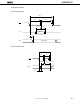
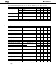
Data Memory Stop Mode Low Supply Voltage Data Retention Characteristics (TA = –40 to +85˚C)
Parameter Symbol Test Conditions MIN. TYP. MAX. Unit
Release signal set time tSREL 0
µ
s
Oscillation stabilization tWAIT Release by RESET
2
15
/f
X
ms
wait time
Note 1
Release by interrupt request
Note 2
ms
Notes 1. The oscillation stabilization wait time is the time during which the CPU operation is stopped to prevent
unstable operation at the start of oscillation.
2. Depends on the basic interval timer mode register (BTM) settings (see the table below).
BTM3 BTM2 BTM1 BTM0 Wait Time
fx = 4.19 MHz fx = 6.0 MHz
—0002
20
/fx (approx. 250 ms) 2
20
/fx (approx. 175 ms)
—0112
17
/fx (approx. 31.3 ms) 2
17
/fx (approx. 21.8 ms)
—1012
15
/fx (approx. 7.81 ms) 2
15
/fx (approx. 5.46 ms)
—1112
13
/fx (approx. 1.95 ms) 2
13
/fx (approx. 1.37 ms)