NEC Projector User Supportware Multi Screen Tool User’s Manual
Introduction Thank you for using the Multi Screen Tool. Please read this User's Manual carefully to aid in the proper use of this product before using the Multi Screen Tool. The Multi Screen Tool is a software application for easy performing stacked projection using the "Geometric Correction" function of NEC projectors and tiled projection using the "Edge Blending" function. This manual mainly describes operations for the NP-PA600 series.
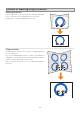
Effects of stacking/tiling correction Stacking correction Create the geometric correction data so that the projected images of two to four projectors are superimposed on one another. Stacking lets you achieve high brightness projections. Tiling correction Create geometric correction data to project a single image using two to four projectors.
Note • The resolution of the projected image is the same as the projector's display resolution. • Enlarge, reduce or mask the projected image of the projector with the same image signal input and create the geometric correction data so that it is contained within the screen (specified projection range) at the beginning. This is not a function for inputting controlled image signals to multiple projectors to form a single projected image.
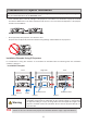
Precautions in Projector Installation For details on the installation precautions, see the operating instructions of the projector you are using. The precautions below are for the NP-PA600 series. • Leave sufficient space to the left and right of the projectors so that there is no obstruction of projector air intake and exhaust. Obstruction of air intake and exhaust will result in a rise of the internal temperature of the projector and will cause breakdown.
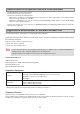
Restrictions on Projectors that Are to Be Installed • • • Install all projectors on the same network. Use projectors with the same resolution. Use the same model to the extent possible. * When there is a difference in the brightness of the projectors, the web camera might not accurately read the projection image at the time of calibration. * Differences in brightness can also be caused by the [ECO MODE] setting. Make the same [ECO MODE] setting on all the installed projectors.
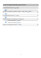
Flow through stacking/tiling correction Install the Multi Screen Tool Page 9 Install and connect the computer, projector, or web camera Setup the Multi Screen Tool Page 17 Make adjustments to the projector or web camera Projector preparation Projector web camera Perform stacking/tiling correction Page 24 Page 26 Page 26 7 Page 13
Table of Contents Effects of stacking/tiling correction................................................................. 3 Precautions in Projector Installation ............................................................... 5 Installation Example Using 2 Projectors ................................................................5 Restrictions on Projectors that Are to Be Installed ........................................ 6 Application Environment of the Multi Screen Tool ..................................
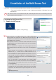
1. Installation of the Multi Screen Tool Preparation: Save the downloaded Multi Screen Tool file to the desired location * The same installation procedure is used for Windows 8/Windows 7/Windows Vista and Windows XP. Note This software cannot be used simultaneously with the Stacking Correction Tool. If the Stacking Correction Tool is already installed, uninstall it. Installing the Multi Screen Tool 1. Double click MSTxxx.exe The installation screen appears. Click [Next (N)]. Note NET Framework 3.
1. Installation of the Multi Screen Tool 2. Select "I accept the terms in the license agreement" and click [Next]. Please read the content of the END USER LICENSE AGREEMENT carefully. A screen for verifying the installation location will be displayed. 3. Click [Next] To change the installation location, click [Change] and specify the installation location. A screen notifying that the installation preparation has been completed will be displayed. 4. Click [Install] The installation will begin.
1. Installation of the Multi Screen Tool Note DirectX 10 & above (DirectX 9 for Windows XP) is required to use this application. When this condition is not satisfied, the screen on the right will be displayed. Please follow the instructions on the screen to complete the set up of DirectX. 6. Click [Next (N)]. A screen asking you where to install the software appears. 7. Click [Install] The installation will start. To change the installation location, click [Browse…] and specify the installation location.
1. Installation of the Multi Screen Tool Uninstallation of the Multi Screen Tool Windows 8/Windows 7/Windows Vista Select the Multi Screen Tool from [Uninstall a program] under [Control Panel] and uninstall it. Windows XP Select the Multi Screen Tool from [Add/Remove Programs] under [Control Panel] and uninstall it.
2. Installation and Connection of Equipment Connections for stacking/tiling correction See page 6 for projectors supporting stacking/tiling correction.
2. Installation and Connection of Equipment Note Common to both cases of using/not using the web camera • Plug each projector into a power outlet. • Connect each of the projectors to the same network. • Use LAN cable that supports Category 5 or higher for the connection to the network. Note Only when using the web camera • Install the web camera facing the projection image. • The photographic coverage of the web camera is 30˚.
2.
2. Installation and Connection of Equipment Make connections as illustrated in the diagrams below when connecting video equipment other than the computer (e.g., DVD players etc.).
3. Multi Screen Tool Settings Starting the Multi Screen Tool For Windows 8 Right click the start screen, and select Multi Screen Tool from [All Apps] to start up. For Windows 7/Windows Vista/Windows XP The same Multi Screen Tool starting method is used for Windows 7/Windows Vista and Windows XP. Select the Multi Screen Tool from [Start] → [All Programs] → [NEC Projector User Supportware] and start it.
3. Multi Screen Tool Settings Stacking ❸ Calibration Mode Master Projector: The projector that will serve as the master is determined, and the projection image of another projector undergoes stacking correction so that it is in agreement with the projection image of the master projector. In this instance, the [GEOMETRIC CORRECTION] of the master projector does not change. Auto: When there is a screen frame, the projection image is corrected so as to fit inside that frame.
3. Multi Screen Tool Settings Multi Screen Tool Menu File Open Save as Open the GCXS file (extension .gcxs) saved with the [Save as] command and send the geometric correction data to all connected projectors. When using a GCXS file to reproduce projected images to which stacking/tiling correction has been applied, make sure the installation and connections of all the projectors are the same as when the GCXS file was saved.
3. Multi Screen Tool Settings Names of the Calibration Screen When using the web camera Calibration Screen ❶ ❷ ❸ ❶ Setup Performs the angle of view check and other camera checks. ❷ Calibrate Starts stacking/tiling correction. When 4-point specification of tiling correction is selected, the 4 corner points of ❸ Update Calibration the projected tile image can be fine-tuned to update the calibration. The correction will finish quickly as pictures will not be taken by the camera.
3. Multi Screen Tool Settings Setup Screen ❽ ❺ ❻ ❶ ❼ ❷ ❸ ❾ ❹ ❶ Camera Settings ❷ Tools Exposure, gain and focus Adjust the camera exposure, gain and focus. Auto-Tune Adjusts to the optimum picture quality for calibration. Show Pattern Displaying the focus pattern Display the focus pattern (15 x 15 dot) in the projector. Reset Point Locations Displayed only when [Tiling] → [4-Point Specification] is selected in the main screen of the Multi Screen Tool.
3. Multi Screen Tool Settings When not using the web camera Calibration Screen ❶ ❷ ❸ ❶ Calibrate ❷ Select Image Boundary ❸ Apply Calibration Set up the region where the projected images overlap. Set up the four corner points of the projected image that will serve as the corrected result. Reflect the corrected result in the projector.
3. Multi Screen Tool Settings Scalable Menu Scalable Menu ❶ ❹ ❷ ❸ ❺ ❻ ❶ Product Info Display the version of the calibration software (EasyStack ™ ). Slider: Enlarge/reduce the UI scale. ❷ UI Scale Auto: Match the UI scale to the window size. Reset: Return the UI scale to the initial setting. ❸ Preferences ❹ Reset Error Actions ❺ Exit Reset the action when an error occurs during correction. Close the calibration screen and return to Multi Screen Tool.
4. Preparation of the Projectors Prepare the projectors to be used for stacking/tiling correction. In addition to the explanations in this manual, also refer to the projectors' operating instructions. 1. Install and connect the projectors that will be used, and project them onto the screen (The portion of projectors that will be used) Connection of the Equipment Page 13 Tiling correction only • Please adjust the projection positions so that the projected image of each projector overlaps by 15% or more.
4. Preparation of the Projectors Note Reference • The [CORNERSTONE] screen will not be displayed when making adjustments with the [KEYSTONE] screen, or when setting [GEOMETRIC CORRECTION]. To perform the [CORNERSTONE] adjustment, hold down the 3D REFORM button for 2 seconds or longer, and clear the [KEYSTONE] adjustment values. Likewise, the [KEYSTONE] screen will not be displayed when making adjustments with the [CORNERSTONE] screen, or when setting [GEOMETRIC CORRECTION].
5. Performing Stacking/Tiling Correction When using the web camera Preparations: Connect the web camera to a computer on which the Multi Screen Tool and the web camera's utility software are installed, then connect the computer to the same LAN as the projectors. Connection of the Equipment To the USB port of the computer Page 13 1. Start the Multi Screen Tool 2.
5. Performing Stacking/Tiling Correction 4. Select the [GEOMETRIC CORRECTION] data storage location The default setting is [1]. Note In the projector, GEOMETRIC CORRECTION data has already been registered in 1 to 3 as the default setting. The existing GEOMETRIC CORRECTION data of the selected number will be overwritten in the saving location by the Multi Screen Tool. 5. Select the type of calibration mode.
5. Performing Stacking/Tiling Correction 8. Click [Calibrate] Calibration will start. Four types of test image (illustrated below) will be projected onto the screen in order. Note • During the calibration, please pay attention to the following points: - Do not touch the installation platform of the camera or projector. - Do not cut across in front of the camera. - Do not let shadows from outside light fall upon the screen. • Press the ESC key on the keyboard to cancel calibration.
5. Performing Stacking/Tiling Correction When not using the web camera Note Windows XP does not support correction when not using the web camera. Preparations: Connect the computer with Multi Screen Tool to the projector using the video cable, and then connect it to the same LAN as the projector. Set up the computer screen settings in duplicates to project the same image in all the projectors.
5. Performing Stacking/Tiling Correction 4. Select the [GEOMETRIC CORRECTION] data storage location The default setting is [1]. Note In the projector, GEOMETRIC CORRECTION data has already been registered in 1 to 3 as the default setting. The existing GEOMETRIC CORRECTION data of the selected number will be overwritten in the saving location by the Multi Screen Tool. 5. Select the type of calibration mode. Select Stacking when doing stacking correction and Tiling when doing tiling correction.
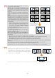
5. Performing Stacking/Tiling Correction 7. Set up the layout (only when performing tiling correction) ❷ Select the layout depending on the ❶ installation ❶ of the projector, ❸ drag the number icon ❹ onto the layout region, and match it to the arrangement projected in the screen. Click [Next] at the end of the placement. The layout that can be selected differs depending on ❷ the number of projectors connected. ❸ Note Reference The figure will not be projected in the projector of [1].
5. Performing Stacking/Tiling Correction 8. Click [Calibrate] 4 points will be projected on Projector 1 when [Calibrate] is clicked. 9. Drag each point onto the region where When performing stacking correction the projected images overlap Move the 4 points displayed in the first projector to the overlapping region of another projector to align the positions of the units in pairs. Press the ENTER key at the end of the operation.
5. Performing Stacking/Tiling Correction 10. Drag the various points onto the region When performing stacking correction set up in the previous step Match the 4 points displayed in the second projector to the 4 points of the first projector specified earlier. Press the ENTER key at the end of the operation. The following operations can be carried out using the various keys of the keyboard. ENTER key Backspace key ESC key ↑↓←→ keys p key n key Proceed to the next step. Return to the previous step.
5. Performing Stacking/Tiling Correction 11. Adjust the various points so that the test images overlap each other Good example Adjust the 4 points placed in the previous step and check the degree of overlap between the 2 projectors. Press the ENTER key at the end of the operation. When there are 3 or more projectors connected, return to Step 9 to adjust the remaining projectors. Return to the main screen at the end of all the adjustments.
5. Performing Stacking/Tiling Correction 12. Click [Select Image Boundary] to set up the 4 corner points of the projected image that will serve as the correction result The test image will be displayed in all the connected projectors. Set up the 4 corners of the projected image in the order starting from top left to top right to lower left to lower right. Return to the main screen at the end of all the settings. The following operations can be carried out using the various keys of the keyboard.
5. Performing Stacking/Tiling Correction Note Reference • When using the web camera, the computer and web camera used for the correction can be removed after the correction. • When GEOMETRIC CORRECTION is set, KEYSTONE and CORNERSTONE cannot be selected. • Hold down the 3D REFORM button for 2 seconds or longer to clear the GEOMETRIC CORRECTION data that has been set.
6. Calibration When using the web camera In calibration, differences in brightness on the screen are identified and calculations are performed. Also, for the purpose of the calculations, the contour of the projection image, and the position and shape of the test image are photographed with a web camera.
6. Calibration After checking the items on the previous pages, if an error still occurs during calibration, it is possible that the quality of the image photographed by the web camera is insufficient and cannot be recognized. Please pay attention to the points described below and make adjustments of the photographic image using the camera setup screen or the utility of the web camera, then try the calibration. • Set up and adjust the camera so that the background of the screen (e.g., walls, etc.
7. List of Error Messages When an error occurs during the calibration and a message is displayed, please refer to the table below and respond as indicated. Reference • Error messages extract a portion of the display content. • Rarely, an error message that is not listed in this manual may be displayed. If this happens, check the photographic image of the camera or the adjustment and position of the camera according to the error message.
Trademarks • Microsoft, Windows, Windows Vista, .NET Framework, and DirectX are either registered trademarks or trademarks of Microsoft Corporation in the United States and other countries. • Powered by Scalable Display Technologies Protected by US Patent 6,456,339 and patents pending • Logitech is a registered trademark of Logitech Inc. • HDMI is a registered trademark or trademark of HDMI Licensing, LLC. © NEC Display Solutions, Ltd. 2011-2013 Ver.