User’s Manual MultiSync LCD4020 MultiSync LCD4620
Index Declaration of conformity ............................................................................................................................. English-1 Important Information ................................................................................................................................... English-2 Warning, Caution ......................................................................................................................................... English-2 Declaration ...
This device complies with Part 15 of FCC Rules. Operation is subject to the following two conditions. (1) This device may not cause harmful interference, and (2) this device must accept any interference received, including interference that may cause undesired operation. U.S. Responsible Party: Address: Tel. No.: NEC Display Solutions of America, Inc.
Important Information WARNING TO PREVENT FIRE OR SHOCK HAZARDS, DO NOT EXPOSE THIS UNIT TO RAIN OR MOISTURE. ALSO, DO NOT USE THIS UNIT’S POLARIZED PLUG WITH AN EXTENSION CORD RECEPTACLE OR OTHER OUTLETS UNLESS THE PRONGS CAN BE FULLY INSERTED. REFRAIN FROM OPENING THE CABINET AS THERE ARE HIGH VOLTAGE COMPONENTS INSIDE. REFER SERVICING TO QUALIFIED SERVICE PERSONNEL. CAUTION CAUTION: TO REDUCE THE RISK OF ELECTRIC SHOCK, MAKE SURE POWER CORD IS UNPLUGGED FROM WALL SOCKET.
• • • FOR OPTIMUM PERFORMANCE, PLEASE NOTE THE FOLLOWING WHEN SETTING UP AND USING THE MULTI-FUNCTION MONITOR: Immediately unplug your monitor from the wall outlet and refer servicing to qualified service personnel under the following conditions: DO NOT OPEN THE MONITOR. There are no user serviceable parts inside and opening or removing covers may expose you to dangerous shock hazards or other risks. Refer all servicing to qualified service personnel. • When the power supply cord or plug is damaged.
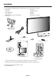
Contents Your new MultiSync LCD4020/MultiSync LCD4620 monitor box* should contain the following: • LCD monitor • Clamp x 3 • Power Cord • Screw (M4 x 10) x 9 • Video Signal Cable • CD-ROM • User’s Manual • Stand x 2 • Wireless Remote Control and AA Batteries • Thumbscrew for stand x 2 • Cable Cover Video Signal Cable (Mini D-SUB 15 pin to Mini D-SUB 15 pin) Power Cord Cable Cover Screw (M4 x 10) x 9 Clamp x 3 Thumbscrew for stand x 2 Stand x 2 VGA RGB/HV OPTION SIZE 1 4 7 DISPLA
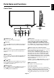
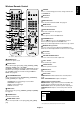
English Parts Name and Functions Control Panel ON OFF 1 POWER button ( ) 7 INPUT button Switches the power on/off. See also page 21. Acts as SET button within OSD menu. (Toggle switches between [DVI], [VGA], [RGB/HV], [HDMI], [DVD/HD], [VIDEO], [S-VIDEO] or [TV]). [S-VIDEO] is enabled by selecting the “SEPARATE” mode in the OSD or by having the “S-VIDEO” cable connected with the “S-VIDEO” signal present and selecting “PRIORITY” MODE. See page 28.
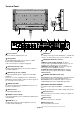
Terminal Panel In Out 1 AC IN connector 9 AUDIO OUT* Connects with the supplied power cord. To output the audio signal from the AUDIO IN 1, 2, 3, HDMI, and TV jack to an external device (stereo receiver, amplifier, etc.). 2 DVI IN (DVI-D) 10 VIDEO INPUT/OUTPUT Connector* To input digital RGB signals from a computer or HDTV device having a digital RGB output. VIDEO IN connector (BNC and RCA): To input a composite video signal.
7 KEYPAD Press to set and change passwords, change channel and set REMOTE ID. 8 ENT button Sets channels. 9 DISPLAY button Turns on/off the information OSD. See page 22. 10 MENU button Turns on/off the menu mode. 11 AUTO SETUP button Enters auto setup menu. See page 24. 12 EXIT button Turns to previous menu with OSD menu. 13 UP/DOWN button button to move the highlighted area up or Acts as down to select the adjustment with OSD menu. Small screen which adjusted “PIP” mode moves up or down.
22 REMOTE ID button Activates REMOTE ID function. Operating Range for the Remote Control 23 MTS button* Multichannel television sound. Point the top of the remote control toward the LCD monitor’s remote sensor during button operation. 24 SLEEP button* Use the remote control within a distance of about 7 m/23 ft. from the front of the LCD monitor’s remote control sensor and at a horizontal and vertical angle of within 30° within a distance of about 3.5 m/10 ft. Sets power off timer.
English Installation This device cannot be used or installed without the Tabletop Stand or other mounting accessory for support. For proper installation it is strongly recommended to use a trained, NEC authorized service person. Failure to follow NEC standard mounting procedures could result in damage to the equipment or injury to the user or installer. Product warranty does not cover damage caused by improper installation. Failure to follow these recommendations could result in voiding the warranty.
Attaching Mounting Accessories 2. Installing and removing stand The display is designed for use with the VESA mounting system. CAUTION: Installing and removing the stand must be done by two or more people. 1. Attach Mounting Accessories How to install stand 1. Please turn monitor off. Mounting accessories can be attached while the monitor is on the Tabletop Stand in the upright position (Figure 1). Be careful to avoid tipping monitor when attaching accessories.
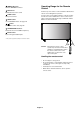
When using the display with the Tabletop Stand fasten the LCD to a wall using a cord or chain that can support the weight of the monitor (approx. LCD4020: 31.1 Kg/LCD4620: 37.9 Kg) in order to prevent the monitor from falling. Fasten the cord or chain to the monitor using the provided clamp and screw. Screw Holes LCD4020: 250mm/LCD4620: 210mm Cord or chain Clamp Screw Before attaching the LCD monitor to the wall, make sure that the wall can support the weight of the monitor.
Setup 1. Determine the installation location NEC recommends the following battery use: CAUTION: Installing your LCD display must be done by a qualified technician. Contact your dealer for more information. • Place “AA” size batteries matching the (+) and (-) signs on each battery to the (+) and (-) signs of the battery compartment. • Do not mix battery brands. • Do not combine new and old batteries. This can shorten CAUTION: MOVING OR INSTALLING THE LCD MONITOR MUST BE DONE BY TWO OR MORE PEOPLE.
11. Recommended Adjustments • Remove the six screws (Figure 4). • Use 6 of the M4 x 10 screws (included) to attach the cable cover (Figure 5). To reduce the risk of the “image persistence”, please adjust the following items based on the application being used: “SCREEN SAVER”, “SIDE BORDER COLOR” (See page 27) “DATE & TIME”, “SCHEDULE SETTINGS” (See page 25). It is recommended that the “FAN CONTROL” setting (See page 27) be turned to ON also. Figure 4 Figure 5 6.
Connections Before making connections: * First turn off the power of all the attached equipment and make connections. * Refer to the user manual included with each separate piece of equipment. Connecting a Personal Computer Connecting your computer to your LCD monitor will enable you to display your computer’s screen image. Some video cards and pixel clock over 165MHz may not display an image correctly. Your LCD monitor displays proper image adjusting the factory preset timing signal automatically.
Connecting your Macintosh computer to your LCD monitor will enable you to display your computer’s screen image. Some video cards or drivers may not display images correctly. Connect the LCD Monitor to Macintosh • To connect the VGA IN connector (mini D-sub 15 pin) on the LCD monitor, use the supplied PC - Video RGB signal cable (mini D-sub 15 pin to mini D-sub 15 pin).
Connecting with Digital Interface Equipment Connections can be made with equipment that is equipped with a digital interface compliant with the DVI (Digital Visual Interface) standard. Connect the LCD Monitor to a Computer with a Digital Output • The DVI IN connector also accepts a DVI-D cable. • Input TMDS signals conforming to DVI standards. • To maintain display quality, use a cable with a quality prescribed by DVI standards. • The AUDIO IN 1, 2 and 3 can be used for audio input.
English Connecting a DVD Player with component out* Connecting your DVD player to your LCD monitor will enable you to display DVD video. Refer to your DVD player user’s manual for more information. Connect the LCD Monitor to a DVD Player • To connect the DVD/HD IN connector (RCA) on the LCD monitor, use a separately available RCA connector cable. Some DVD players may have different connectors such as DVI-D connector. Select [DVI/HD] mode from the “DVI MODE” menu when you connect a DVI-D connector.
Connecting a DVD Player with HDMI out* Connecting your DVD player to your LCD monitor will enable you to display DVD video. Refer to your DVD player user’s manual for more information. Select [HDMI] from the AUDIO INPUT button. Connect the LCD Monitor to a DVD Player • Please use the HDMI cable with HDMI logo. • You may need some seconds to show the signal. • We do not support PC-DVI signal. LCD monitor To HDMI output HDMI connector *: The product you purchased may not have this feature.
You can connect your stereo amplifier to your LCD monitor. Refer to your amplifier owner’s manual for more information. Connect the LCD Monitor to a Stereo Amplifier • Turn on the LCD monitor and the amplifier only after all connections have been made. • Use a stereo Mini-RCA cable to connect the AUDIO OUT connector (Stereo Mini Jack) on the LCD monitor and the audio input on the amplifier. • Do not reverse the audio left and right jacks. • The AUDIO IN is used for audio input.
Connecting to a TV* Precautions when connecting the antenna • Use a coaxial cable which is free from interference. Avoid using a parallel flat wire as interference may occur, causing the reception to become unstable and noise to appear on the screen. • Avoid using an indoor antenna as this may be affected by interference and poor reception. • Cable distribution system should be grounded (earthed) in accordance with ANSI/NFPA 70, the National Electrical Code (NEC), in particular Section 820.
English Basic Operation Power ON and OFF Modes The LCD monitor power indicator will turn green while powered on and will turn red while powered off. NOTE: The Main Power Switch must be in the ON position in order to power up the monitor using the remote control or the Power Button on the front of the LCD.
Power Indicator Mode Power ON Power OFF (Eco Standby)*1 Power consumption under 1W Power OFF (Standby) Power consumption under 5W Power Save Power Standby when “SCHEDULE SETTINGS” enabled Diagnosis (Detecting failure) Status Indicator Light Green*2 Red Amber Amber Blinking Green and Amber blink alternately Red Blinking (See Troubleshooting page 35) *1 When in Eco Standby Mode RS-232C controls do not function.
English OSD (On-Screen-Display) Controls Input source Main Menu Icons Main Menu Item Adjustment Settings Sub Menu ADAPTIVE CONTRAST Select Goto Adjustment Return Close Key Guide Press UP or DOWN button to select sub-menu. Press SET. Press UP or DOWN, PLUS or MINUS to select the function or setting to be adjusted. Press MENU or EXIT. Press UP or DOWN button to select. Press INPUT button to decide. Press UP or DOWN, PLUS or MINUS button to select.
OSD PICTURE Setting BRIGHTNESS Adjusts the overall image and background brightness. Press + or - to adjust. CONTRAST Adjusts the image brightness in relationship to the background. Press + or - to adjust. Note: The sRGB picture mode is standard and cannot be changed. SHARPNESS Adjusts the crispness of the image. Press + or - to adjust. BLACK LEVEL Adjusts the image brightness in relationship to the background. Press + or - to adjust. TINT* Adjusts the tint of the screen. Press + or - to adjust.
Adjusts the horizontal size of the image. INPUT DVI, VGA, RGB/HV only V RESOLUTION Adjusts the vertical size of the image. INPUT DVI, VGA, RGB/HV only ZOOM MODE Select the aspect ratio of the screen image. BASE ZOOM 16:9* For input sources that have a 16:9 aspect ratio. 14:9* For input sources that have a 14:9 aspect ratio. DYNAMIC* Expands 4:3 picture to fill the screen. Some of the image is lost due to expansion. OFF Selecting “OFF” will display the image in a 1 by 1 pixel format.
TIME DAYLIGHT SAVING PIP SCHEDULE RESET Resets the following settings within the SCHEDULE menu back to factory setting: OFF TIMER, SCHEDULE SETTINGS. KEEP PIP MODE* Allows the monitor to remain in “PIP” mode after powering off. When Power is returned, PIP appears without having to enter the OSD.
Resets the following settings within the OSD menu back to factory setting: OSD TURN OFF, OSD POSITION, INFORMATION OSD, OSD TRANSPARENCY. MONITOR ID Sets the monitor ID number from 1-26. IR CONTROL Selects the mode of the monitor for use with the infra-red remote control when using the RS-232C daisy chain. NORMAL The monitor will be controlled normally by wireless remote controller. PRIMARY Choose “PRIMARY” for the first monitor within an RS-232C daisy chain.
ADVANCED OPTION INPUT DETECT except TV input Selects the method of input detection the monitor uses when more than two input devices are connected. NONE The Monitor will not search the other video input ports. FIRST DETECT When the current video input signal is not present, then the monitor searches for a video signal from the other video input port. If the video signal is present in the other port, then the monitor switches the video source input port to the new found video source automatically.
Some video formats may require scan conversion in order to best display the image. INPUT HDMI, DVD/HD, VIDEO, TV only TV TUNER* OVER SCAN Image size is larger than what can be displayed. The image edge will appear cropped. Approximately 95% of the image will be shown on the screen. UNDER SCAN Image size stays within the display area. The whole image is displayed on the screen.
NOTE 2: IMAGE PERSISTENCE Please be aware that LCD Technology may experience a phenomena known as Image Persistence. Image Persistence occurs when a residual or “ghost” image of a previous image remains visible on the screen. Unlike CRT monitors, LCD monitors’ image persistence is not permanent, but constant images being displayed for a long period of time should be avoided. To alleviate image persistence, turn off the monitor for as long as the previous image was displayed.
MONITOR ID and IR CONTROL Using one PC or one infrared wireless controller, up to 26 individual LCD4020/LCD4620 monitors can be controlled through a daisy chain via RS-232C connection. 1. Connect PC and LCD4020/LCD4620. Connect a PC’s RS-232C control output to the LCD4020/LCD4620’s RS-232C input. You can then connect the RS-232C output from the LCD4020/LCD4620 to another LCD4020/LCD4620’s RS-232C input. Up to 26 monitors can be connected using RS-232C. 2. Set Monitor ID and IR Control mode.
Controlling the LCD monitor via RS-232C Remote Control This LCD monitor can be controlled by connecting a personal computer with a RS-232C terminal.
(1) The command from a computer to the LCD monitor will be sent in 400ms. (2) The LCD monitor will send a return command 400ms* after it has received and encoded. If the command isn’t received correctly, the LCD monitor will not send the return command. (3) The personal computer checks the command and confirms if the command, which has been sent, has been executed or not. (4) This LCD monitor sends various codes other than return code.
Features Reduced Footprint: Provides the ideal solution for environments requiring superior image quality but with size and weight limitations. Colour Control Systems: Allows you to adjust the colours on your screen and customize the colour accuracy of your monitor to a variety of standards. OmniColor: Combines Six-axis colour control and the sRGB standard.
No picture • The signal cable should be completely connected to the display card/computer. • The display card should be completely seated in its slot. • Front Power Switch and computer power switch should be in the ON position. • Check to make sure that a supported mode has been selected on the display card or system being used. (Please consult display card or system manual to change graphics mode.
Specifications - LCD4020 Product Specifications LCD Module Pixel Pitch: Resolution: Colour: Brightness: Contrast Ratio: Viewing Angle: Design View Distance: Frequency Horizontal: Vertical: 40" /101.6cm diagonal 0.648mm 1366 x 768 dots Over 16 million colours (depending on video card used) 700cd/m2 (Max.), 500cd/m2 (Typ.) 1200:1 Up 89°/ Down 89°/ Left 89°/ Right 89° (typ) @ CR>10 1100mm 15.625/15.734kHz, 31.5kHz - 91.1kHz (Analog Input) 31.5kHz - 91.1kHz (Digital Input) 50.0 - 85.0 Hz Pixel Clock 25.
English Specifications - LCD4620 Product Specifications LCD Module Pixel Pitch: Resolution: Colour: Brightness: Contrast Ratio: Viewing Angle: Design View Distance: Frequency Horizontal: Vertical: 46" /116.8cm diagonal 0.7455mm 1366 x 768 dots Over 16 million colours (depending on video card used) 650cd/m2 (Max.), 500cd/m2 (Typ.) 1200:1 Up 89°/ Down 89°/ Left 89°/ Right 89° (typ) @ CR>10 1300mm 15.625/15.734kHz, 31.5kHz - 91.1kHz (Analog Input) 31.5kHz - 91.1kHz (Digital Input) 50.0 - 85.
Pin Assignment 1) Analog RGB input (MiniDsub15p): VGA Pin No Name 1 Video Signal Red 2 Video Signal Green 3 Video Signal Blue 4 GND 5 DDC-GND 6 Red-GND 7 Green-GND 8 Blue-GND Mini D-SUB 15P 1 9 +5V (DDC) 10 SYNC-GND 11 GND 12 DDC-SDA 13 H-SYNC 14 V-SYNC 15 DDC-SCL 5 6 10 11 15 2) S-VIDEO input: VIDEO Pin No Name 1 GND 2 GND 3 Y (Luminance) 4 C (Chroma) 3) Digital RGB input (DVI-D): DVI Pin - Assignment of DVI connector: 1 TX2- 9 TX1- 17 TX0- 2 TX2+ 10 T
NEC DISPLAY SOLUTIONS is strongly committed to environmental protection and sees recycling as one of the company’s top priorities in trying to minimize the burden placed on the environment. We are engaged in developing environmentallyfriendly products, and always strive to help define and comply with the latest independent standards from agencies such as ISO (International Organisation for Standardization) and TCO (Swedish Trades Union).