MultiSync LCD4010 40" LCD Colour Monitor MultiSync LCD4610 46" LCD Colour Monitor User’s Manual
Index Declaration of conformity ............................................................................................................................. English-1 Important Information ................................................................................................................................... English-2 Warning, Caution ......................................................................................................................................... English-2 Declaration ...
This device complies with Part 15 of FCC Rules. Operation is subject to the following two conditions. (1) This device may not cause harmful interference, and (2) this device must accept any interference received, including interference that may cause undesired operation. U.S. Responsible Party: Address: Tel. No.: NEC Display Solutions of America, Inc.
Important Information WARNING TO PREVENT FIRE OR SHOCK HAZARDS, DO NOT EXPOSE THIS UNIT TO RAIN OR MOISTURE. ALSO, DO NOT USE THIS UNIT’S POLARIZED PLUG WITH AN EXTENSION CORD RECEPTACLE OR OTHER OUTLETS UNLESS THE PRONGS CAN BE FULLY INSERTED. REFRAIN FROM OPENING THE CABINET AS THERE ARE HIGH VOLTAGE COMPONENTS INSIDE. REFER SERVICING TO QUALIFIED SERVICE PERSONNEL. CAUTION CAUTION: TO REDUCE THE RISK OF ELECTRIC SHOCK, MAKE SURE POWER CORD IS UNPLUGGED FROM WALL SOCKET.
FOR OPTIMUM PERFORMANCE, PLEASE NOTE THE FOLLOWING WHEN SETTING UP AND USING THE MULTISYNC LCD4010 / MULTISYNC LCD4610 LCD COLOUR MONITOR: • • • Immediately unplug your monitor from the wall outlet and refer servicing to qualified service personnel under the following conditions: DO NOT OPEN THE MONITOR. There are no user serviceable parts inside and opening or removing covers may expose you to dangerous shock hazards or other risks. Refer all servicing to qualified service personnel.
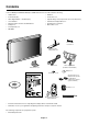
Contents Your new MultiSync LCD4010 / MultiSync LCD4610 monitor box* should contain the following: • LCD monitor • Band x 2 • Power Cord (3m) • Ferrite Core x 2 • Video Signal Cable — SC-B113 (4m) • Speaker Plug x 1set (Required for optional Loudspeakers) • User’s Manual • Stand for the Independence x 2 • Wireless Remote Control and AA Batteries • Thumbscrew for stand x 2 • Clamper x 3 • Main switch cover • Screw (M4 x 8) x 4 • CD-ROM Thumbscrew for stand x 2 Stand for the Indep
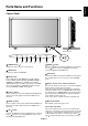
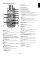
English Parts Name and Functions Control Panel 9 EXIT INPUT MUTE 10 Button Location EXIT INPUT MUTE OFF 8 7 6 5 4 3 2 ON 1 1 POWER button ( ) 7 DOWN ( ) button Switches the power on/off. See also page 18. Activates the OSM menu when the OSM menu is turned-off. Acts as button to move the highlighted area down to select the adjustment with OSM menu. 2 MUTE button Switches the audio mute ON/OFF. 8 EXIT button 3 INPUT button Acts as SET button within OSM menu.
Terminal Panel 1 AC IN connector 7 AUDIO IN 1, 2, 3 Connects with the supplied power cord. To input audio signal from external equipment such as a computer, VCR or DVD player. 2 RGB 1 IN (DVI-D) 8 AUDIO OUT To input digital RGB signals from a computer or HDTV device having a digital RGB output. To output the audio signal from the AUDIO IN 1, 2 and 3 jack. * This connector does not support analog input.
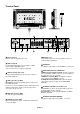
6 MUTE button To switch the mute function on/off. 7 VOLUME UP button Increases the audio output level. 8 VOLUME DOWN button Decreases the audio output level. 9 PIP (Picture In Picture) button ON/OFF button: Toggle switches between PIP, POP, side-by-side (aspect) and side-by-side (full). See page 23. INPUT button: Selects the “picture in picture” input signal. CHANGE button: Replaces to the main picture and sub picture. 10 STILL button ON/OFF button: To switch the still picture mode on/off.
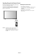
Operating Range for the Remote Control Point the top of the remote control toward the LCD monitor’s remote sensor during button operation. Handling the remote control Use the remote control within a distance of about 7 m/23 ft. from the front of the LCD monitor’s remote control sensor and at a horizontal and vertical angle of within 30° within a distance of about 3 m/10 ft. * Do not subject to strong shock. * Do not allow water or other liquid to splash the remote control.
1. Determine the installation location 3. Connect external equipment (See pages 12-17) CAUTION: DO NOT ATTEMPT TO INSTALL THE LCD MONITOR BY YOURSELF. Installing your LCD display must be done by a qualified technician. Contact your dealer for more information. CAUTION: MOVING OR INSTALLING THE LCD MONITOR MUST BE DONE BY TWO OR MORE PEOPLE. Failure to follow this caution may result in injury if the LCD monitor falls. CAUTION: Do not mount or operate the display upside down, face up, or face down.
10. Recommended Adjustment To reduce the risk of “image persistence”, please adjust the following items based on the application being used. “SCREEN SAVER” (See page 24), “SIDE BORDER COLOR” (See page 24), “DATE & TIME” (See page 28), “SCHEDULE” (See page 28). 11. When the monitor is installed in the portrait position • Remove the stands (feet). • Left edge should be the upper edge from front view. 12. Installing and removing stand Speaker terminal How to install stand 1. Please turn monitor off. 2.
You can attach mounting accessories to the LCD monitor in one of the following two ways: 3. Ventilation Requirements for enclosure mounting 1. In the upright position To allow heat to disperse, leave space between surrounding objects as shown in the diagram below. 4. To avoid falling down Fasten the LCD monitor to wall using a cord or chain, which is sufficient to support the weight of the LCD monitor (approx. LCD4010: 27,5kg / LCD4610: 35,7kg). 250mm 2.
Connections Before making connections: * First turn off the power of all the attached equipment and make connections. * Refer to the user manual included with each separate piece of equipment. Wiring Diagram LCD monitor Personal computer DVD player Personal computer VCR Equipment with digital interface Attaching the Ferrite Core LCD monitor (second monitor) Mounting Position of Ferrite Core Attach the Ferrite Core to PC Audio Cable.
Connecting your computer to your LCD monitor will enable you to display your computer’s screen image. Some video cards may not display an image correctly. Resolution 640 x 480 800 x 600 1024 x 768 1280 x 768 1360 x 768 1280 x 1024 1600 x 1200 Scanning frequency Horizontal Vertical 31.5kHz 60Hz 37.9kHz 60Hz 48.
Connecting to a Macintosh Computer Connecting your Macintosh computer to your LCD monitor will enable you to display your computer’s screen image. Some video cards or drivers may not display images correctly. Connect the LCD Monitor to Macintosh • To connect the RGB 2 IN connector (mini D-sub 15 pin) on the LCD monitor, use the supplied PC - Video RGB signal cable (mini D-sub 15 pin to mini D-sub 15 pin).
Connections can be made with equipment that is equipped with a digital interface compliant with the DVI (Digital Visual Interface) standard. Connect the LCD Monitor to a Computer with a Digital Output • The RGB 1 IN connector also accepts a DVI-D cable. • Input TMDS signals conforming to DVI standards. • To maintain display quality, use a cable with a quality prescribed by DVI standards. • The AUDIO IN 1, 2 and 3 can be used for audio input.
Connecting a DVD Player with component out Connecting your DVD player to your LCD monitor will enable you to display DVD video. Refer to your DVD player user’s manual for more information. Connect the LCD Monitor to a DVD Player To connect the DVD/HD IN connector (BNC) on the LCD monitor, use a separately available BNC connector cable. You will need a BNC-to-RCA adapter to connect a DVD player with an RCA pin jack to the BNC connector cable (not provided).
You can connect your stereo amplifier to your LCD monitor. Refer to your amplifier owner’s manual for more information. Connect the LCD Monitor to a Stereo Amplifier • Turn on the LCD monitor and the amplifier only after all connections have been made. • Use an RCA cable to connect the AUDIO OUT connector (RCA) on the LCD monitor and the audio input on the amplifier. • Do not reverse the audio left and right jacks. • The AUDIO IN is used for audio input.
Basic Operation Power ON and OFF Modes The LCD monitor power indicator will turn green while powered on, or red when in off mode. The monitor can be powered on or off using the following three options: 1. Pressing the power button. Note: Before pressing the power button, be sure to turn on the Main Power Switch on the LCD monitor. Power Button 2. Using the remote control. Note: Before operating the remote control, be sure to turn on the Main Power Switch on the LCD monitor. 3.
Status Power ON Green Power OFF Red Power Standby when Red On “SCHEDULE” is enable Green Blinking Power Standby Diagnosis (Detecting failure) Red, Green Red Blinking ZOOM Image can be expanded beyond the active display area. The image which is outside of active diaplay area is not displayed. ZOOM * See troubleshooting on page 33 Using Power Management The LCD monitor follows the VESA approved DPM Power Management function.
OSM (On-Screen-Manager) Controls Press MENU button to open Main menu. Press UP or DOWN button to select sub-menu. Press SET button to decide. Press UP or DOWN, and PLUS or MINUS button to select function, or control which you like. Press SET button to decide. Press MENU or EXIT button to exit. Press UP or DOWN button to select. Press INPUT button to decide. Press UP or DOWN, and PLUS or MINUS button to select function, or control which you like. Press INPUT button to decide.
BRIGHTNESS CONTRAST SHARPNESS TINT COLOR BLACK LEVEL NOISE REDUCTION TINT TINT 32 + -:ADJ EXIT :RETURN MENU :EXIT MENU Press + button to Skin colour becomes greenish. Press - button to Skin colour becomes purplish. :SEL SET :NEXT EXIT :RETURN MENU :EXIT MENU *:INPUT DVD/HD, VIDEO only Adjust the colour depth of the screen. PICTURE BRIGHTNESS CONTRAST SHARPNESS TINT COLOR BLACK LEVEL NOISE REDUCTION COLOR COLOR 32 + -:ADJ EXIT :RETURN MENU :EXIT MENU Press + button to increase colour depth.
V RESOLUTION *:INPUT RGB1/2/3 only SCREEN H POSITION V POSITION CLOCK CLOCK PHASE H RESOLUTION V RESOLUTION ZOOM MODE SCREEN RESET V RESOLUTION 768 + -:ADJ EXIT :RETURN MENU :EXIT MENU :SEL SET :NEXT EXIT :RETURN MENU :EXIT MENU SCREEN H POSITION V POSITION CLOCK CLOCK PHASE H RESOLUTION V RESOLUTION ZOOM MODE SCREEN RESET ZOOM MODE CUSTOM OFF :SEL SET :NEXT EXIT :RETURN MENU :EXIT MENU :SEL SET :NEXT EXIT :RETURN MENU :EXIT MENU Adjusts the vertical size by increasing or decreasing the setting.
MAIN MENU PICTURE SCREEN AUDIO PIP CONFIGURATION 1 CONFIGURATION 2 ADVANCED OPTION PICTURE IN PICTURE :SEL SET :NEXT EXIT :RETURN MENU :EXIT MENU Sub-Menu PIP PIP SIZE PIP AUDIO PIP RESET PIP SIZE Selecting the size of picture inserted at the “Picture-in-Picture” (PIP) mode. PIP SIZE LARGE MIDDLE SMALL EXIT :RETURN MENU :EXIT MENU :SEL “Large”, “Middle” and “Small” are available.
SCREEN SAVER CONFIGURATION 1 AUTO SETUP AUTO ADJUST AUTO BRIGHTNESS POWER SAVE LANGUAGE SCREEN SAVER SIDE BORDER COLOR :SEL SET :NEXT EXIT :RETURN MENU :EXIT MENU COLOR SYSTEM *:INPUT VIDEO only SIDE BORDER COLOR CONFIGURATION 1 POWER SAVE LANGUAGE SCREEN SAVER COLOR SYSTEM SIDE BORDER COLOR CONFIGURATION RESET FACTORY RESET :SEL SET :NEXT EXIT :RETURN MENU :EXIT MENU CONFIGURATION 1 AUTO BRIGHTNESS POWER SAVE LANGUAGE POWER SAVE COLOR SYSTEM SIDE BORDER COLOR CONFIGURATION RESET FACTORY RESET SCREEN
RED/GREEN/BLUE DELAY To adjust the each phase of RED, GREEN and BLUE signal. LEVEL: 0 - 6 LONG CABLE MANUAL *:INPUT RGB2/3 only CONFIGURATION 2 LONG CABLE ON/OFF LONG CABLE MANUAL OSM TURN OFF INFORMATION OSM OFF TIMER OSM POSITION INPUT DETECT MONITOR INFORMATION :SEL SET :NEXT EXIT :RETURN MENU :EXIT MENU LONG CABLE MANUAL RED DELY GREEN DELAY BLUE DELAY RED SHARPNESS GREEN SHARPNESS BLUE SHARPNESS SOG PEAK VIDEO EQ.
Selects the method of input detection when more than two computers are connected. FIRST DETECT: When the current video input signal is not present, then the monitor searches for a video signal from the other video input port. If the video signal is present in the other port, then the monitor switches the video source input port to the new found video source automatically. The monitor will not look for other video signals while the current video source is present.
:SEL SET :NEXT EXIT :RETURN MENU :EXIT MENU SCAN MODE ADVANCED OPTION S-VIDEO MODE BLACK LEVEL EXPANSION GAMMA SELECTION IMAGE FLIP SCAN MODE SCAN CONVERSION FILM MODE IMAGE FLIP NORMAL H MIRROR V MIRROR ROTATE :SEL SCAN CONVERSION Changes the display area of the image.
HEAT STATUS ADVANCED OPTION HEAT STATUS STATUS COOLING FAN1 COOLING FAN2 BRIGHTNESS TEMPERATURE SENSOR 1 0.0 C SENSOR 1 0.0 C MONITOR ID IR CONTROL TILE MATRIX HEAT STATUS POWER ON DELAY DATE & TIME SCHEDULE ADVANCED OPTION RESET EXIT :SEL SET :NEXT EXIT :RETURN MENU :EXIT MENU :RETURN ON ON NORMAL / 32.0 F / 32.0 F MENU :EXIT MENU Adjusts the delay time from “standby” to “power on” mode.
4. Please use "Screen Saver Mode" of monitor. NOTE 2: MONITOR ID and IR CONTROL Using the one PC or one infra-red wireless controller, you can control up to 26 MultiSync LCD4010 / MultiSync LCD4610 that are connected by daisy chained RS-232C. 1. Connect a PC and MultiSync LCD4010 / MultiSync LCD4610. Connect a PC’s RS-232C control output to the MultiSync LCD4010’s / MultiSync LCD4610’s RS-232C input.
Controlling the LCD monitor via RS-232C Remote Control This LCD monitor can be controlled by connecting a personal computer with a RS-232C terminal.
(1) The command from a computer to the LCD monitor will be sent in 400ms. (2) The LCD monitor will send a return command 400ms* after it has received and encoded. If the command isn’t received correctly, the LCD monitor will not send the return command. (3) The personal computer checks the command and confirms if the command, which has been sent, has been executed or not. (4) This LCD monitor sends various codes other than return code.
Features Reduced Footprint: Provides the ideal solution for environments requiring superior image quality but with size and weight limitations. The monitor’s small footprint and low weight allow it to be moved or transported easily from one location to another. Colour Control Systems: Allows you to adjust the colours on your screen and customize the colour accuracy of your monitor to a variety of standards. OmniColor: Combines Six-axis colour control and the sRGB standard.
No picture • The signal cable should be completely connected to the display card/computer. • The display card should be completely seated in its slot. • Front Power Switch and computer power switch should be in the ON position. • Check to make sure that a supported mode has been selected on the display card or system being used. (Please consult display card or system manual to change graphics mode.) • Check the monitor and your display card with respect to compatibility and recommended settings.
Specifications for MultiSync LCD4010 Product Specifications Analog Input LCD Module 40" / 101.6cm diagonal 0.648mm 1366 x 768 dots Over 16 million colours (depending on video card used) 450cd/m2 (Typ.) 1000:1 Up 85°/ Down 85°/ Left 85°/ Right 85° (typ) @ CR>10 1100mm Pixel Pitch: Resolution: Colour: Brightness: Contrast Ratio: Viewing Angle: Design View Distance: Frequency Digital Input Horizontal: 15.625/15.734kHz, 31.5kHz - 91.1kHz Vertical: 50.0/58.0 - 85.0 Hz Pixel Clock 25.0MHz - 162.
Product Specifications Analog Input LCD Module 46" / 116.8cm diagonal 0.7455mm 1366 x 768 dots Over 16 million colours (depending on video card used) 500cd/m2 (Typ.) 1000:1 Up 89.5°/ Down 89.5°/ Left 89.5°/ Right 89.5° (typ) @ CR>10 1300mm Pixel Pitch: Resolution: Colour: Brightness: Contrast Ratio: Viewing Angle: Design View Distance: Frequency Digital Input Horizontal: 15.625/15.734kHz, 31.5kHz - 91.1kHz Vertical: 50.0/58.0 - 85.0 Hz Pixel Clock 25.0MHz - 162.0MHz Viewable Size 1018.4 x 572.
Pin Assignment 1) Analog RGB input (MiniDsub15p): R G B 2 Pin No Name 1 Video Signal Red 2 Video Signal Green 3 Video Signal Blue 4 GND 5 DDC-GND 6 Red-GND 7 Green-GND 8 Blue-GND Mini D-SUB 15P 1 9 +5V (DDC) 10 SYNC-GND 11 GND 12 DDC-SDA 13 H-SYNC 14 V-SYNC 15 DDC-SCL 5 6 10 11 15 2) S-VIDEO input: V I D E O Pin No Name 1 GND 2 GND 3 Y (Luminance) 4 C (Chroma) 3) Digital RGB input (DVI-D): R G B 1 Pin - Assignment of DVI connector: 8 1 TX2- 9 TX1- 17 TX0-