User’s Manual MultiSync LCD4020 MultiSync LCD4620 MultiSync LCD5220
Index Declaration of conformity ............................................................................................................................. English-1 Important Information ................................................................................................................................... English-2 Warning, Caution ................................................................................................................................ English-2 Declaration ............
This device complies with Part 15 of FCC Rules. Operation is subject to the following two conditions. (1) This device may not cause harmful interference, and (2) this device must accept any interference received, including interference that may cause undesired operation. U.S. Responsible Party: Address: Tel. No.: NEC Display Solutions of America, Inc.
Important Information WARNING TO PREVENT FIRE OR SHOCK HAZARDS, DO NOT EXPOSE THIS UNIT TO RAIN OR MOISTURE. ALSO, DO NOT USE THIS UNIT’S POLARIZED PLUG WITH AN EXTENSION CORD RECEPTACLE OR OTHER OUTLETS UNLESS THE PRONGS CAN BE FULLY INSERTED. REFRAIN FROM OPENING THE CABINET AS THERE ARE HIGH VOLTAGE COMPONENTS INSIDE. REFER SERVICING TO QUALIFIED SERVICE PERSONNEL. CAUTION CAUTION: TO REDUCE THE RISK OF ELECTRIC SHOCK, MAKE SURE POWER CORD IS UNPLUGGED FROM WALL SOCKET.
FOR OPTIMUM PERFORMANCE, PLEASE NOTE THE FOLLOWING WHEN SETTING UP AND USING THE MULTI-FUNCTION MONITOR: • Recommended Use DO NOT OPEN THE MONITOR. There are no user serviceable parts inside and opening or removing covers may expose you to dangerous shock hazards or other risks. Refer all servicing to qualified service personnel. • For optimum performance, allow 20 minutes for warm-up. • Rest your eyes periodically by focusing on an object at least 5 feet away. Blink often.
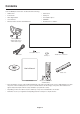
Contents Your new MultiSync monitor box* should contain the following: • LCD monitor • Cable Cover • Power Cord*1 • Clamp x 3 • Video Signal Cable • Screw (M4 x 10) x 9 • User’s Manual • CD-ROM • Wireless Remote Control and AA Batteries • Thumbscrew for stand x 2 Video Signal Cable (Mini D-SUB 15 pin to Mini D-SUB 15 pin) Screw (M4 x 10) x 9 Thumbscrew for stand x 2 Power Cord*1 Clamp x 3 User’s Manual CD-ROM Cable cover User’s Manual Wireless Remote Control and AA Batteries *1 Ty
This device cannot be used or installed without the Tabletop Stand or other mounting accessory for support. For proper installation it is strongly recommended to use a trained, NEC authorized service person. Failure to follow NEC standard mounting procedures could result in damage to the equipment or injury to the user or installer. Product warranty does not cover damage caused by improper installation. Failure to follow these recommendations could result in voiding the warranty.
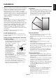
2. Installing and removing optional table top stand Attaching Mounting Accessories The display is designed for use with the VESA mounting system. CAUTION: Installing and removing the stand must be done by four or more people (LCD5220), by two or more people (LCD4020/LCD4620). 1. Attach Mounting Accessories Be careful to avoid tipping monitor when attaching accessories. To install, follow those instructions included with the stand or mounting apparatus.
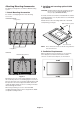
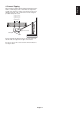
When using the display with the Tabletop Stand fasten the LCD to a wall using a cord or chain that can support the weight of the monitor in order to prevent the monitor from falling. Fasten the cord or chain to the monitor using the provided clamp and screw. LCD4020: 278 mm LCD4620: 210 mm LCD5220: 400 mm Screw Holes Cord or chain Clamp Screw Before attaching the LCD monitor to the wall, make sure that the wall can support the weight of the monitor.
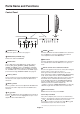
Parts Name and Functions Control Panel ON LCD4020/LCD4620 OFF LCD5220 1 POWER button ( ) 7 DOWN ( ) button Switches the power on/off. See also page 21. Activates the OSD menu when the OSD menu is turned-off. Acts as button to move the highlighted area down to select adjustment items within OSD menu. 2 MUTE button (LCD5220 only) Switches the audio mute ON/OFF. 8 EXIT button 3 INPUT button Acts as SET button within OSD menu.
English Terminal Panel LCD4020/LCD4620 LCD5220 In Out 1 AC IN connector 10 VIDEO INPUT/OUTPUT Connector* Connects with the supplied power cord. VIDEO IN connector (BNC and RCA): To input a composite video signal. BNC and RCA connectors are not available at the same time (Use only one input). VIDEO OUT connector (BNC): To output the composite video signal from the VIDEO IN connector. S-VIDEO IN connector (Mini DIN 4 pin): To input the S-video (Y/C separate signal). See page 28, S-VIDEO MODE SETTING.
Wireless Remote Control 7 KEYPAD Press buttons to set and change passwords, change channel and set REMOTE ID. 8 ENT button* Sets channels. 9 DISPLAY button Turns on/off the information OSD. See page 22. 10 MENU button Turns on/off the menu mode. 11 AUTO SETUP button Enters auto setup menu. See page 24. 12 EXIT button Returns to previous menu within OSD menu. 13 UP/DOWN button button to move the highlighted area up or Acts as down to select adjustment items within OSD menu.
MTS button* Multichannel television sound. SLEEP button Sets power off timer. GUIDE button* Operating Range for the Remote Control Point the top of the remote control toward the LCD monitor’s remote sensor during button operation. Use the remote control within a distance of about 7 m (23 ft.) from the front of the LCD monitor’s remote control sensor or at a horizontal and vertical angle of within 30° within a distance of about 3.5 m (10 ft.) Enters on screen program guide (For U.S.).
Setup 1. Determine the installation location CAUTION: Installing your LCD display must be done by a qualified technician. Contact your dealer for more information. CAUTION: MOVING OR INSTALLING THE LCD MONITOR MUST BE DONE BY FOUR OR MORE PEOPLE (LCD5220), BY TWO OR MORE PEOPLE (LCD4020/LCD4620). Failure to follow this caution may result in injury if the LCD monitor falls. NOTE: If you do not intend to use the Remote Control for a long period of time, remove the batteries. 3.
[For LCD5220] [For LCD4020] • Remove the six screws (Figure 8). • Remove the six screws (Figure 4). • • Use six of the M4 x 10 screws (included) to attach the cable cover (Figure 5). Use six of the M4 x 10 screws (included) to attach the cable cover (Figure 9). Figure 4 Figure 8 Figure 9 Figure 5 [For LCD4620] • Remove the three screws (Figure 6). • Use five of the M4 x 10 screws (included) to attach the cable cover (Figure 7). Figure 6 6.
Connections Before making connections: * First turn off the power of all the attached equipment and make connections. * Refer to the user manual included with each separate piece of equipment.
English Connecting a Personal Computer Connecting your computer to your LCD monitor will enable you to display your computer’s screen image. Some video cards and a pixel clock over 162MHz may not display an image correctly. Your LCD monitor displays proper image by adjusting the factory preset timing signal automatically. Resolution 640 x 480 800 x 600 1024 x 768 1280 x 768 1360 x 768 1280 x 1024 1600 x 1200 1920 x 1080 Scanning frequency Horizontal Vertical 31.5kHz 60Hz 37.
Connecting to a Macintosh Computer Connecting your Macintosh computer to your LCD monitor will enable you to display your computer’s screen image. Some video cards or drivers may not display images correctly. Connect the LCD Monitor to Macintosh • To connect the VGA IN connector (mini D-sub 15 pin) on the LCD monitor, use the supplied PC - Video RGB signal cable (mini D-sub 15 pin to mini D-sub 15 pin).
Connections can be made with equipment that is equipped with a digital interface that complies with the DVI (Digital Visual Interface) standard. Connect the LCD Monitor to a Computer with a Digital Output • The DVI IN connector also accepts a DVI-D cable. • Input TMDS signals conforming to DVI standards. • To maintain display quality, use a cable that conforms to DVI standards. • AUDIO IN* 1, 2 and 3 can be used for audio input.
Connecting a DVD Player with component out* Connecting your DVD player to your LCD monitor will enable you to display DVD video. Refer to your DVD player user’s manual for more information. Connect the LCD Monitor to a DVD Player • To connect the DVD/HD IN connector (RCA) on the LCD monitor, use an RCA connector cable (sold separately). Some DVD players may have different connectors such as DVI-D connector. Select [DVI/HD] mode from the “DVI MODE” menu. For mode selection, see “DVI MODE” on page 28.
Connecting your DVD player to your LCD monitor will enable you to display DVD video. Refer to your DVD player user’s manual for more information. Select [HDMI] from the AUDIO INPUT button. Connect the LCD Monitor to a DVD Player • Please use an HDMI cable with HDMI logo. • It may take a moment for the signal to appear. • PC-DVI signals are not supported.
Connecting to a Stereo Amplifier* You can connect your stereo amplifier to your LCD monitor. Refer to your amplifier owner’s manual for more information. Connect the LCD Monitor to a Stereo Amplifier • Turn on the LCD monitor and the amplifier only after all connections have been made. • Use a stereo Mini-RCA cable to connect the AUDIO OUT* connector (Stereo Mini Jack) on the LCD monitor to the audio input on the amplifier. • Do not reverse the audio left and right jacks.
English Basic Operation Power ON and OFF Modes The LCD monitor power indicator will turn green while powered on and will turn red or amber while powered off. NOTE: The Main Power Switch must be in the ON position in order to power up the monitor using the remote control or the Power Button on the front of the LCD.
NORMAL: Displays the aspect ratio the same as it is sent from the source. FULL: Fills entire screen. WIDE*: Expands a 16:9 letter box signal to fill entire screen. ZOOM (DYNAMIC): Expands a 4:3 pictures to fill the entire screen with non-linearity. Some of the outside image area will be cut off due to expansion.
English OSD (On-Screen-Display) Controls NOTE: Some functions may not be available depending on the model or optional equipment. Input source Main Menu Icons Main Menu Item Adjustment Settings Sub Menu ADAPTIVE CONTRAST Select Goto Adjustment Return Close Key Guide Press UP or DOWN button to select sub-menu. Press SET. Press UP or DOWN, PLUS or MINUS to select the function or setting to be adjusted. Press MENU or EXIT. Press UP or DOWN button to select. Press INPUT button to decide.
Setting Default PICTURE BRIGHTNESS Adjusts the overall image and background brightness. Press + or - to adjust. *1 CONTRAST Adjusts the image brightness in relationship to the background. Press + or - to adjust. Note: The sRGB picture mode is standard and cannot be changed. *2 SHARPNESS Adjusts the crispness of the image. Press + or - to adjust. *3 BLACK LEVEL Adjusts the image brightness in relationship to the background. Press + or - to adjust.
Adjusts the visual “noise” on the image. - Adjusts the horizontal size of the image. - Adjusts the vertical size of the image. - Select the aspect ratio of the screen image. - VGA, RGB/HV, DVD/HD inputs only H RESOLUTION DVI, VGA, RGB/HV inputs only V RESOLUTION DVI, VGA, RGB/HV inputs only ZOOM MODE Does not work with TV input in the U.S. BASE ZOOM 16:9 CUSTOM For input sources that have a 16:9 aspect ratio.
PIP KEEP PIP MODE* Allows the monitor to remain in “PIP” and “TEXT TICKER” mode after powering off. When Power is returned, PIP and TEXT TICKER appear without having to enter the OSD. OFF PIP MODE* Picture-in-Picture OFF OFF OFF PIP PIP POP POP SIDE BY SIDE (ASPECT) SIDE BY SIDE ASPECT SIDE BY SIDE (FULL) PIP SIZE SIDE BY SIDE FULL Selects the size of the sub-picture used in Picture-in-Picture (PIP) mode. LARGE SMALL MIDDLE LARGE PIP POSITION Determines where the PIP appears on the screen.
MONITOR ID Sets the monitor ID number from 1-26. IR CONTROL Selects the mode of the monitor for use with the infra-red remote control when using the RS-232C daisy chain. NORMAL The monitor will be controlled normally by wireless remote controller. PRIMARY Choose “PRIMARY” for the first monitor within an RS-232C daisy chain. SECONDARY Choose “SECONDARY” for all subsequent monitors within an RS-232C daisy chain. LOCK Prevents the monitor from being controlled by wireless remote controller.
ADVANCED OPTION INPUT DETECT All inputs except for TV Selects the method of input detection the monitor uses when more than two input devices are connected. NONE The Monitor will not search the other video input ports. FIRST DETECT When the current video input signal is not present, then the monitor searches for a video signal from the other video input port.
SCAN MODE* Some video formats may require different scanning modes in order to best display the image. OVER SCAN HDMI, DVD/HD, VIDEO, TV inputs only OVER SCAN Image size is larger than what can be displayed. The image edge will appear cropped. Approximately 95% of the image will be shown on the screen. UNDER SCAN Image size stays within the display area. The whole image is displayed on the screen.
Connecting to a TV* (For U.S.) Initial TV Setup Before watching TV for the first time it is necessary to program the channels. 1. Attach the cable or antenna to the coaxial RF Connector on the side of the monitor. 5. Once channels are in memory, use the CHANNEL EDIT menu to add or remove channels. Use the CHANNEL LABELS menu to create unique names for channels, if desired.
OFF No Limitation. TV-Y All children. The themes and elements in this program are specifically designed for a very young audience, including children from ages 2-6. TV-Y7 Directed to older children. Themes and elements in this program may include mild physical or comic violence or may frighten children under the age of 7. TV-G General audience. It contains little or no violence, no strong language, and little or no suggestive dialogue or situations. TV-PG Parental guidance suggested.
Connecting to a TV* (For Europe) Precautions when connecting the antenna • Use a coaxial cable which is free from interference. Avoid using a parallel flat wire as interference may occur, causing the reception to become unstable and noise to appear on the screen. • Avoid using an indoor antenna as this may be affected by interference and poor reception. • Cable distribution system should be grounded (earthed) in accordance with ANSI/NFPA 70, the National Electrical Code (NEC), in particular Section 820.
NOTE 1: CREATING A SCHEDULE English The schedule function allows the display to be set to power on and off at different times. Up to seven different schedules can be programmed. To program the schedule: 1. Enter the SCHEDULE menu. Highlight SCHEDULE SETTINGS using the up and down buttons. Press the SET or the + button to enter the Settings menu. Highlight the desired schedule number and press set. The box next to the number will turn yellow. The schedule can now be programmed. 2.
Remote Control ID Function REMOTE CONTROL ID The remote control included with the display can be used to control up to 26 individual MultiSync monitors using what is called the REMOTE CONTROL ID mode. The REMOTE CONTROL ID mode works in conjunction with the Monitor ID, allowing control of up to 26 individual MultiSync monitors. For example: if there are many monitors being used in the same area, a remote control in normal mode would send signals to every monitor at the same time Figure 1.
Monitor ID: Displays the ID number of the current monitor within the daisy chain. Target ID: Displays the ID number of the monitor that to be controlled via daisy chain from the current monitor. Press the “+” or “-” buttons to change the “Target ID” to show the ID number of the monitor to be controlled. To control the entire daisy chained monitors simultaneously, select “ALL” as the “Target ID.” 4. Use the wireless remote controller to control the “SECONDARY” monitor while aiming at the “PRIMARY” monitor.
Controlling the LCD monitor via RS-232C Remote Control This LCD monitor can be controlled by connecting a personal computer with a RS-232C terminal.
Reduced Footprint: Provides the ideal solution for environments requiring superior image quality but with size and weight limitations. Color Control Systems: Allows you to adjust the colors on your screen and customize the color accuracy of your monitor to a variety of standards. OmniColor: Combines Six-axis color control and the sRGB standard. Six-axis color control permits color adjustments via six axes (R, G, B, C, M and Y) rather than through the three axes (R, G and B) previously available.
Troubleshooting No picture • The signal cable should be completely connected to the display card/computer. • The display card should be completely seated in its slot. • Front Power Switch and computer power switch should be in the ON position. • Check to make sure that a supported mode has been selected on the display card or system being used. (Please consult display card or system manual to change graphics mode.
Product Specifications LCD Module Pixel Pitch: Resolution: Color: Brightness: Contrast Ratio: Viewing Angle: Design View Distance: Frequency Horizontal: Vertical: 40" /101.6 cm diagonal 0.648 mm 1366 x 768 dots Over 16 million colors (depending on video card used) 700 cd/m2 (Max.), 500 cd/m2 (Typ.) 2000:1 89° (typ) @ CR>10 1100 mm 15.625/15.734 kHz, 31.5 kHz - 91.1 kHz (Analog Input) 31.5 kHz - 91.1 kHz (Digital Input) 50.0 - 85.0 Hz Pixel Clock 25.2 MHz - 162.0 MHz Viewable Size 885.168 x 497.
Specifications - LCD4620 Product Specifications LCD Module Pixel Pitch: Resolution: Color: Brightness: Contrast Ratio: Viewing Angle: Design View Distance: Frequency Horizontal: Vertical: 46" /116.8 cm diagonal 0.648 mm 1366 x 768 dots Over 16 million colors (depending on video card used) 650 cd/m2 (Max.), 500 cd/m2 (Typ.) 2000:1 89° (typ) @ CR>10 1300 mm 15.625/15.734 kHz, 31.5 kHz - 91.1 kHz (Analog Input) 31.5 kHz - 91.1 kHz (Digital Input) 50.0 - 85.0 Hz Pixel Clock 25.2 MHz - 162.
Product Specifications LCD Module Pixel Pitch: Resolution: Color: Brightness: Contrast Ratio: Viewing Angle: Design View Distance: Frequency Horizontal: Vertical: 52" /132.1 cm diagonal 0.6 mm 1920 x 1080 dots Over 16 million colors (depending on video card used) 700 cd/m2 (Max.), 500 cd/m2 (Typ.) 2000:1 89° (typ) @ CR>10 1400 mm 15.625/15.734 kHz, 31.5 kHz - 91.1 kHz (Analog Input) 31.5 kHz - 91.1 kHz (Digital Input) 50.0 - 85.0 Hz Pixel Clock 25.2 MHz - 162.
Pin Assignment 1) Analog RGB input (MiniDsub15p): VGA Pin No Name 1 Video Signal Red 2 Video Signal Green 3 Video Signal Blue 4 GND Mini D-SUB 15P 1 5 DDC-GND 6 Red-GND 7 Green-GND 8 Blue-GND 9 +5V (DDC) 10 SYNC-GND 11 GND 12 DDC-SDA 13 H-SYNC 14 V-SYNC 15 DDC-SCL 5 6 10 11 15 2) S-VIDEO input: VIDEO Pin No Name 1 GND 2 GND 3 Y (Luminance) 4 C (Chroma) 3) Digital RGB input (DVI-D): DVI Pin - Assignment of DVI connector: 1 TX2- 9 TX1- 17 2 TX2+ 3 Shield (
NEC DISPLAY SOLUTIONS is strongly committed to environmental protection and sees recycling as one of the company’s top priorities in trying to minimize the burden placed on the environment. We are engaged in developing environmentallyfriendly products, and always strive to help define and comply with the latest independent standards from agencies such as ISO (International Organisation for Standardization) and TCO (Swedish Trades Union).