
Configuration Guide


Table Of Contents
- Technical Specification
- External Views
- Configuration Diagram
- Server Configuration
- 1 Base Models
- 2 2nd Processor
- 3 Memory
- 4 Internal Hard Disk Drives
- 4.1 RAID Configuration
- 4.2 Internal Drive Configuration
- 4.2.1 2.5-inch Drives with On-board SATA Controller
- 4.2.2 Up to eight 2.5-inch Drives with RAID 0/1 Controller with 256 MB Cache
- 4.2.3 Up to eight 2.5-inch Drives with RAID 5/6 Controller with 256 MB Cache
- 4.2.4 Up to eight 2.5-inch Drives with RAID 5/6 Controller with 512 MB Cache
- 4.2.5 Up to twelve 2.5-inch Drives with RAID 0/1 Controller with 256 MB Cache
- 4.2.6 Up to twelve 2.5-inch Drives with RAID 5/6 Controller with 256 MB Cache
- 4.2.7 Up to twelve 2.5-inch Drives with RAID 5/6 Controller with 512 MB Cache
- 4.2.8 3.5-inch Drives with On-board SATA Controller
- 4.2.9 3.5-inch Drives with RAID 0/1 Controller with 256 MB Cache
- 4.2.10 3.5-inch Drives with RAID 5/6 Controller with 256 MB Cache
- 4.2.11 3.5-inch Drives with RAID 5/6 Controller with 512 MB Cache
- 5 Optical Drive
- 6 Floppy Drive / Flash FDD
- 7 Internal Tape / RDX Drives
- 8 PCI Riser Card / PCI Card
- 9 Other Add-in Components
- 10 Add-on Components
- 11 Support Service
- References
- Revision History
CONFIGURATION GUIDE – NEC EXPRESS5800/R120b-2
NEC Corporation Revision 5.2, September 2011 10
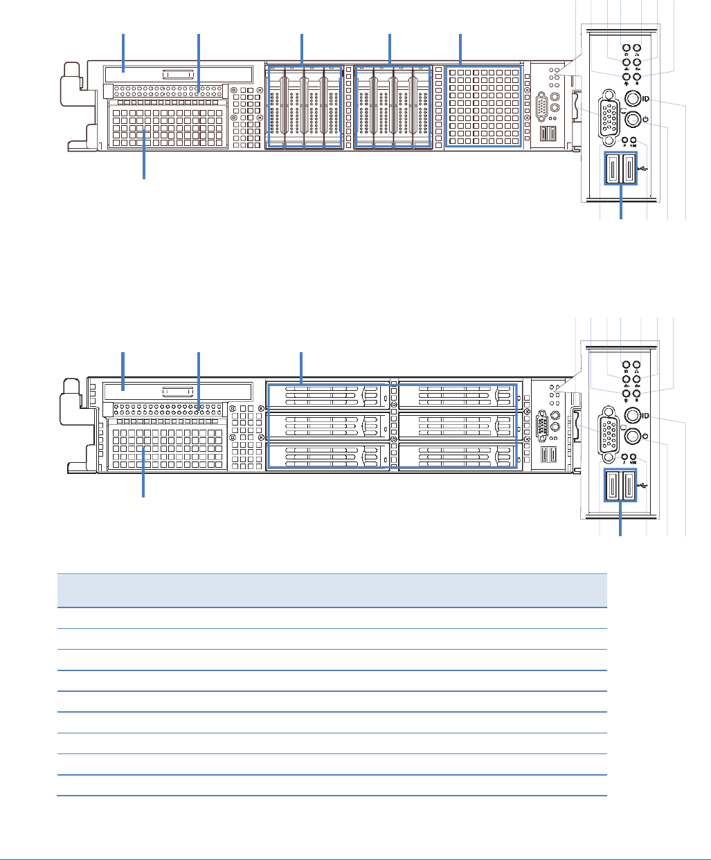
External Views
Front and Rear Views
Front View for 2.5-inch Drive Model
Front View for 3.5-inch Drive Model
Legend
A.
Optical Drive Bay
J.
Data LAN 2 Activity LED
B.
Floppy Drive Bay
K.
Hard Drive Activity LED
C.
Drive Bays
L.
3.5-inch Media Bay
D.
2.5-inch Drive Cage Bay
M.
System Reset Switch
E.
VGA Connector
N.
USB Connectors
F.
Power LED
O.
Dump (NMI) Switch
G.
Data LAN 1 Activity LED
P.
Power Button
H.
UID LED
Q.
UID LED Button
I.
System Status LED
A B C
L
D
E F G H I J K
M N O P Q
C
A B C
L
E F G H I J K
M N O P Q