
User's Guide


System Upgrade 8-49
N8803-031F in pairs. Insert one into a slot in a PCI module and the other
one into the slot at the same location in the other PCI module.
After starting the system with the N8803-031F installed, make settings of
the SCSI topology.
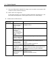
PCI Board Status LED Indications
LED indications
Fail LED State LED
Description Action
Off Amber
The Fibre Channel disk
array device is not
connected yet, or not
connected correctly (not
duplicated)
Check the connection to the
Fibre Channel disk array
device. (For details, see the
instruction manual of the Fibre
Channel disk array device.)
Off Green
The PCI board is
operating normally in
duplex mode.
-
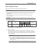
Off Off
The PCI board is not
installed yet, the PCI
board is installed
incorrectly, or the power is
not supplied.
Mount the PCI board correctly.
If the PCI board was not
mounted, there is no problem.
Check the condition of power
unit.
Remount the PCI module.
Red Amber
The PCI board is on a
software control test, or is
preparing for the
operation.
Wait for a while until the
indication changes. If the
indication does not change,
check the status of the
installed PCI board slot using
NEC ESMPRO Manager.
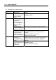
Red Off
Although the PCI board is
mounted, it may be offline
or not be working.
Make the installed PCI board
slot online from NEC
ESMPRO Manager.
Mount the PCI board correctly.
Configure SCSI topology
If you expanded the FC board to the PCI slot, configuration of the topology is needed. Follow
the procedure below to set the topology:
1. Decide the domain number on which the setting is performed from the /proc/scsi/scsi file
and the /proc/scsi/topo file. Execute the following command from the shell:
echo setdomain number>/proc/scsi/topo
2. Decide any SCSI bus number which is not used, and then execute the following command
from the shell:
echo bus number_type PCI_BUS_NO:PCI_SLOT_NO.CHANNEL_NO>/proc/scsi/topo
number is a SCSI bus number. type is a device type (e.g., qla2x00). PCI_BUS_NO is ‘01’
for the FC controller board of the PCI module 1, ‘40’ for the FC controller board of the
PCI module 2. PCI_SLOT_NO is a number of PCI slots (in ascending order (0, 1, 2…)
from the left). CHANNEL_NO is a channel number (the first channel is ‘00’). For the set
of “type” and “PCI_BUS_NO:PCI_SLOT_NO.CHANNEL_NO”, if there are more than