
user manual


ND-45504 (E) CHAPTER 4
Addendum-001 Page 78-5
JULY, 1998 Revision 2.1
PN-30DTC/30DTC-A (DTI)
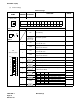
Note 3:
Set SW-1 and SW-2 as follows.
Note 4:
Coaxial cable connection to the PN-30DTC/30DTC-A is not available in the U.S.
DTI 0DTI 1DTI 2DTI 3
REMARKS
SW-1 SW-2 SW-1 SW-2 SW-1 SW-2 SW-1 SW-2
When one DTI is provided. ON OFF
The MP card will receive the clock
signal from DTI 0 at its PLO 0 input.
When more than one DTI
is provided.
ON OFF OFF ON OFF OFF OFF OFF
The MP card will receive the clock
signal from DTI 0 at its PLO 0 input,
under normal conditions.
Should a clock failure occur on
DTI 0, the MP card will automatical-
ly switch to the PLO 1 input, and so
derive the clock from DTI 1.
No. of DTI
CONDITIONS
SW