
user manual


CHAPTER 4 ND-45504 (E)
Page 78-4 Addendum-001
Revision 2.1 JULY, 1998
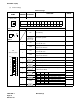
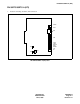
PN-30DTC/30DTC-A (DTI)
The figure in the SWITCH NAME column and the position in in the SETTING POSITION col-
umn indicate the standard setting of the switch. When the switch is not set as shown by the figure and
, the setting of the switch varies with the system concerned.
Note 1: Set the groove on the switch knob to the intended switch position.
Note 2: When the power is on, set the MB switch to ON (UP position) before plugging/unplugging the circuit
card.
JPS
(Jumper pin)
Balanced transmission
(For twisted-pair cable)
DOWN
TA is grounded on the transmission line
(For coaxial cable)
Note 4
JPR
(Jumper pin)
Balanced transmission
(For twisted-pair cable)
DOWN
RA is grounded on the transmission line
(For coaxial cable)
JP
(Jumper pin)
RIGHT
Line impedance: 75 ohms
(For coaxial cable)
Note 4
Line impedance: 120 ohms
(For twisted-pair cable)
Switch Settings
SWITCH
NAME
SWITCH
NUMBER
SETTING
POSITION
FUNCTION CHECK
UP
UP
LEFT