
user manual


ND-45504 (E) CHAPTER 4
Page 77
Revision 2.0
PN-24DTA-A (DTI)
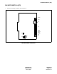
The figure in the SWITCH NAME column and the position in in the SETTING POSITION col-
umn indicate the standard setting of the switch. When the switch is not set as shown by the figure and
, the setting of the switch varies with the system concerned.
Note 1:
Set the groove on the switch knob to the intended switch position.
Note 2:
When the power is on, flip the MB switch to ON (UP position) before plugging/unplugging the circuit
card.
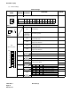
Switch Settings (Continued)
SWITCH
NAME
SWITCH
NUMBER
SETTING
POSITION
FUNCTION CHECK
JPS (Jumper pin)
Neutral grounding on the transmitting line is not provid-
ed.
Left Neutral grounding on the transmitting line is provided.
JPR0 (Jumper pin)
Right Neutral grounding on the receiving line is provided.
Neutral grounding on the receiving line is not provided.
JPR1 (Jumper pin)
Right Line impedance : 110 ohms
Line impedance : 100 ohms
AISS (Jumper pin)
AIS signal is sent out when make-busy or power on.
Left AIS signal is not sent out when make-busy or power on.
MAS (Jumper pin)
Right When this card is used for factory testing.
When this card is used for normal operation.
Right
Left
Left
Right
Left