
user manual


CHAPTER 4 ND-45504 (E)
Page 76
Revision 2.0
PN-24DTA-A (DTI)
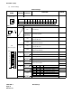
(3) Switch Settings
Switch Settings
SWITCH
NAME
SWITCH
NUMBER
SETTING
POSITION
FUNCTION CHECK
SENS
(Rotary SW)
Note 1
4 ~ F Set the switch to match the AP Number (04 ~ 15) to be set by CM05.
0 ~ 3
Not used
MB (Toggle SW)
Note 2
UP For make-busy
For normal operation
SW
(Piano Key SW)
1
ON
Clock signal from a master office is sent to the PLO 0 in-
put on the MP card.
OFF
Clock signal from a master office is not sent to the PLO
0 input on the MP card.
2
ON
Clock signal from a master office is sent to the PLO 1 in-
put on the MP card.
OFF
Clock signal from a master office is not sent to the PLO
1 input on the MP card.
3
ON
Remote loop-back
For normal operation
4
ON
Local loop-back (AIS send)
For normal operation
5
Set the equalizer according to the cable length between
the PBX and the MDF.
OFF
6
OFF
7
OFF
8 Always set to ON
AP NO.
SW NO.
1004 05 06 07 08 09 11 12 13 14 15
456789ABCDEF
ON
DOWN
ON
OFF
4
3
2
1
5
6
7
8
OFF
OFF
ON
SW-5 SW-6 SW-7 CABLE LENGTH
ON ON ON 0 - 40 m ( 0 - 131.2 ft.)
ON ON OFF 40 - 80 m (131.2 - 262.5 ft.)
ON OFF ON 80 - 120 m (262.5 - 394 ft.)
ON OFF OFF 120 - 160 m (394 - 525 ft.)
OFF ON ON 160 - 200 m (525 - 656 ft.)
OFF OFF OFF Signal is not sent
ON
ON
ON