
user manual


CHAPTER 4 ND-45504 (E)
Page 64
Revision 2.0
PN-BRTA (BRI)
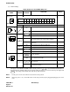
(3) Switch Settings
The figure in the SWITCH NAME column and the position in in the SETTING POSITION col-
umn indicate the standard setting of the switch. When the switch is not set as shown by the figure and
, the setting of the switch varies with the system concerned.
Note 1:
Set the groove on the switch knob to the desired switch position.
Note 2:
When the power is on, set the MB switch to ON (UP position) before plugging/unplugging the circuit
card.
Switch Settings on the PN-BRTA (BRI) Card
SWITCH
NAME
SWITCH
NUMBER
SETTING
POSITION
FUNCTION CHECK
SENS
(Rotary SW)
Note 1
4 - F Set the switch to match the AP Number (04 - 15) as set by CM05.
0 - 3 Not used
MB (Toggle SW)
Note 2
UP
For make-busy
For normal operation
SW0 (Dip SW)
1
For normal operation (BRI mode)
OFF Not used
2
Note 3
ON
Clock signal from a master office is sent to the PLO of
MP card according to the switch setting of SW0-3.
OFF
Clock signal from a master office is not sent to the PLO
of MP card.
3
Note 3
ON Clock signal is sent to PLO 0 of MP card.
OFF Clock signal is sent to PLO 1 of MP card.
4
For normal operation
OFF Not used
SW1 (Dip SW)
1
For terminating the transmitting side of channels B1 and
B2 with 100 ohms.
OFF
To remove the terminating resistor on the transmitting
side of channels B1 and B2.
2
For terminating the receiving side of channels B1 and B2
with 100 ohms.
OFF
To remove the terminating resistor on the receiving side
of channels B1 and B2.
0
AP NO.
SW NO.
1004 05 06 07 08 09 11 12 13 14 15
456789ABCDEF
ON
DOWN
ON
4321
ON
ON
ON
21
ON
ON