
user manual


ND-45504 (E) CHAPTER 4
Page 61
Revision 2.0
PN-AP01 (AP01)
The figure in the SWITCH NAME column and the position in in the SETTING POSITION col-
umn indicate the standard setting of the switch. When the switch is not set as shown by the figure and
, the setting of the switch varies with the system concerned.
Note 1:
Set the groove on the switch knob to the desired switch position.
Note 2:
When the power is on, flip the MB switch to ON (UP position) before plugging/unplugging the circuit
card.
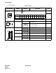
SW0 (Dip SW) 1 Always set to OFF
2 Always set to OFF
3 Always set to OFF
4
Always set to OFF
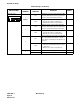
Switch Settings (Continued)
SWITCH NAME
SWITCH
NUMBER
SETTING
POSITION
FUNCTION CHECK
1 2 3 4
ON
OFF
OFF
OFF
OFF