
user manual


CHAPTER 4 ND-45504 (E)
Page 58
Revision 2.0
PN-AP00-A (AP00)
Note 1:
Set the groove on the switch knob to the desired switch position.
Note 2:
When the power is on, flip the MB switch to ON (UP position) before plugging/unplugging the circuit
card.
Note 3:
The SW 1 is used to select the AP operating mode as shown below.
On line : Normal operating mode. The AP should be always in the “On line”, other than when you delete the AP
data.
Off line : The mode for AP data clearing by the command CMD100/CMD101.
Note 4:
The use of the external clock (from the distant end) or the internal clock is determined by the following
table:
Note 5:
When the DCE connected to the port does not provide a function to send the DSR signals, set the switch
to ON. In this case, the AP00 card can not recognize the actual state of the DCE, so that the call records
or system messages will not be stored in the memory buffer on the AP00 card even if the cable is discon-
nected from the DCE.
When the switch is set to OFF, the call records or system messages will be stored when the cable is dis-
connected, and will be sent when the cable is re-connected.
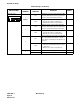
SWITCH ON LINE OFF LINE
SW 1-4 OFF OFF
SW 1-3 ON OFF
SW 1-2 ON OFF
SW 1-1 ON ON
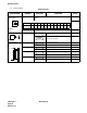
CLOCK
SW0
15
External ON OFF
Internal OFF ON