
user manual


ND-45504 (E) CHAPTER 4
Page 57
Revision 2.0
PN-AP00-A (AP00)
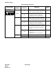
The figure in the SWITCH NAME column and the position in in the SETTING POSITION col-
umn indicate the standard setting of the switch. When the switch is not set as shown by the figure and
, the setting of the switch varies with the system concerned.
Switch Settings (Continued)
SWITCH NAME
SWITCH
NUMBER
SETTING
POSITION
FUNCTION CHECK
SW0
5
Note 4
ON
• Uses the internal clock as the receive
clock when the No. 0 Port is synchro-
nous.
• When the No. 0 Port is asynchronous.
OFF
Enables receive clock from the DCE (Mo-
dem) side when the No. 0 Port is synchro-
nous. (Clock is received at the RXC
terminal)
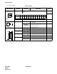
6
Note 5
ON
Set No. 0 port forcibly in a state which DSR
signal is always provided. Force DSR sig-
nal high for port 0. No SMDR buffering.
OFF
Receive DSR signal from the DCE on No.
0 port. Detect DSR signal from DCE for
port 0. Allows SMDR records to buffer.
7
Note 5
ON
Set No. 1 port forcibly in a state which DSR
signal is always provided. Force DSR sig-
nal high for port 1. No SMDR buffering.
OFF
Receive DSR signal from the DCE on No.
1 port. Detect DSR signal from DCE for
port 1. Allows SMDR records to buffer.
8
Note 5
ON
Set No. 2 port forcibly in a state which
DSR signal is always provided. Force DSR
signal high for port 2. No SMDR buffering.
OFF
Receive DSR signal from the DCE on No.
2 port. Detect DSR signal from DCE for
port 2. Allows SMDR records to buffer.