
user manual


ND-45504 (E) CHAPTER 4
Addendum-002 Page 41
OCTOBER, 1998 Revision 2.2
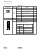
PN-CP02/PN-CP02-C (MP)
The figure in the SWITCH NAME column and the position in in the SETTING POSITION col-
umn indicate the standard setting of the switch. When the switch is not set as shown by the figure and
, the setting of the switch varies with the system concerned.
Note 1: Set the groove on the switch to the desired switch position.
Note 2: On the stand by status circuit card, the SW3 can be set to only “0” or “B”. Do not set to the other
position (1-9, A, C-F).
Note 3: MP0 and MP1 must not set to “ON” at the same time.
Note 4: When the power is on, flip the MB switch to ON (UP position) before plugging/unplugging the circuit
card.
Switch Settings (Continued)
SWITCH NAME
SWITCH
NUMBER
SETTING
POSITION
FUNCTION CHECK
SW2 (Piano Key SW)
2, 3
• When using the PLO card (PN-CK00):
• When not using the internal PLO and the PLO card:
4 ~ 7 Not used
8
Note 3
ON Allowed to use MAT
For normal operation
(Not allowed to use MAT)
JP0 (Jumper pin)
For normal operation
Memory backup connected
DOWN
For factory test only
(Disconnect battery for memory backup.)
SW4 (Toggle SW)
Note 4
UP For make-busy
For normal operation
ON
OFF
7
8
5
4
3
2
1
6
SW2-2
OFF
SW2-3
ON
SW2-2
OFF
SW2-3
OFF
OFF
OFF
Front
UP
ON
DOWN