
user manual


CHAPTER 4 ND-45504 (E)
Page 38
Revision 2.0
PN-CP01 (FP)
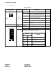
(3) Switch Settings
The figure in the SWITCH NAME column and the position in in the SETTING POSITION col-
umn indicate the standard setting of the switch. When the switch is not set as shown by the figure and
, the setting of the switch varies with the system concerned.
Note 1:
Set the groove on the switch knob to the desired switch position.
Note 2:
When the power is on, flip the MB switch to ON (UP position) before plugging/unplugging the circuit
card.
Note 3:
The PN-CP01 is required only if any of the following is true:
• More than one PIM is used.
• A PN-2DLCC is used.
• A PN-AP01 is used.
• OAI, ACD, No. 7 CCIS, or ISDN is used.
Switch Settings
SWITCH NAME
SWITCH
NUMBER
SETTING
POSITION
FUNCTION CHECK
SW1 (Rotary SW)
Note 1
0 – 3
Set this rotary switch to match the location in which this cir-
cuit card is to be mounted.
0 For mounting this card in PIM0
1 For mounting this card in PIM2
2 For mounting this card in PIM4
3 For mounting this card in PIM6
4 – F Not used
MB (Toggle SW)
Note 2
UP For make-busy
For normal operation
ON
DOWN