
user manual


CHAPTER 4 ND-45504 (E)
Page 128
Revision 2.0
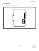
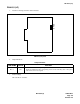
PN-M03 (M03)
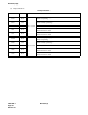
(3) Switch Settings
Note:
The JP1A and JP1B must be set to the same position each other.
The figure in the SWITCH NAME column and the position in in the SETTING POSITION col-
umn indicate the standard setting of the switch. When the switch is not set as shown by the figure and
, the setting of the switch varies with the system concerned.
Switch Settings
SWITCH
NAME
SWITCH
NUMBER
SETTING
POSITION
FUNCTION CHECK
SW0 (Dip SW)
1
Always set to OFF.
2
Not used.
JP1A (Jumper pin)
Note
TXC(2) signal is sent out.
Left
TXC(2) signal is inputted.
JP1B (Jumper pin)
Note
TXC(2) signal is sent out.
Left
TXC(2) signal is inputted.
OPSD (Jumper pin)
Right
Set the function of extending distance for TXD signal.
Cancel the function of extending distance for TXD sig-
nal.
OPRS (Jumper pin)
Right
Set the function of extending distance for RTS signal.
Cancel the function of extending distance for RTS sig-
nal.
OPER (Jumper pin)
Right
Set the function of extending distance for DTR signal.
Cancel the function of extending distance for DTR sig-
nal.
2
ON
1
OFF
OFF
Right
Right
Left
Left
Left