
user manual


ND-45504 (E) CHAPTER 4
Page 123
Revision 2.0
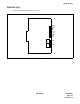
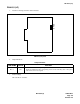
PN-2ILCA (ILC)
(3) Switch Settings
The figure in the SWITCH NAME column and the position in in the SETTING POSITION col-
umn indicate the standard setting of the switch. When the switch is not set as shown by the figure and
, the setting of the switch varies with the system concerned.
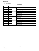
Switch Settings
SWITCH
NAME
SWITCH
NUMBER
SETTING
POSITION
FUNCTION CHECK
SW1
(Piano Key SW)
1
Always set to OFF
2
Always set to OFF
3
Always set to OFF
4
Always set to OFF
SW0
(Piano Key SW)
1
No. 0 Circuit
(Receiving)
Terminating register is provided.
OFF Terminating register is not provided.
2
No. 0 Circuit
(Sending)
Terminating register is provided.
OFF Terminating register is not provided.
3
No. 1 Circuit
(Receiving)
Terminating register is provided.
OFF Terminating register is not provided.
4
No. 1 Circuit
(Sending)
Terminating register is provided.
OFF Terminating register is not provided.
ON
OFF
4
3
2
1
OFF
OFF
OFF
OFF
ON
OFF
4
3
2
1
ON
ON
ON
ON