
user manual


CHAPTER 4 ND-45504 (E)
Page 120
Revision 2.0
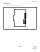
PN-2DPCB (DPC)
(3) Switch Settings
The figure in the SWITCH NAME column and the position in in the SETTING POSITION col-
umn indicate the standard setting of the switch. When the switch is not set as shown by the figure
and , the setting of the switch varies with the system concerned.
Note:
When the power is on, disconnect the cables before unplugging the circuit card, and connect the cables af-
ter plugging the circuit card.
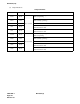
Switch Settings
SWITCH NAME
SWITCH
NUMBER
SETTING
POSITION
FUNCTION CHECK
SW1
(Piano Key SW)
1
ON
No. 0
Circuit
Loop Back 1 ON
Loop Back 1 OFF
2
ON Loop Back 2 ON
Loop Back 2 OFF
3
ON
No. 1
Circuit
Loop Back 1 ON
Loop Back 1 OFF
4
ON Loop Back 2 ON
Loop Back 2 OFF
SW0 (Dip SW)
1
ON
No. 0
Circuit
Forcibly turning the DTR signal to ON
OFF The DTR signal from DTE goes through the card
2
ON Forcibly turning the RTS/C signal to ON
OFF The RTS/C signal from DTE goes through the card
3 Not used
4
ON V.11 (X.21) interface
OFF V.24/V.28 (RS-232C) interface
5
ON
No. 1
Circuit
Forcibly turning the DTR signal to ON
OFF The DTR signal from DTE goes through the card
6
ON Forcibly turning the RTS/C signal to ON
OFF The RTS/C signal from DTE goes through the card
7 Not used
8
ON V.11 (X.21) interface
OFF V.24/V.28 (RS-232C) interface
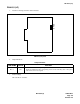
ON
4
3
2
1
OFF
OFF
OFF
OFF
OFF
ON
12345678
OFF
OFF