
user manual


ND-45504 (E) CHAPTER 4
Page 87
Revision 2.0
PN-4RSTC (CIR)
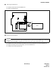
(3) Switch Settings
Note 1:
Set the groove on the switch knob onto the desired switch position.
Note 2:
When the power is on, flip the MB switch to ON (UP position) before plugging/unplugging the circuit
card.
Switch Settings
SWITCH
NAME
SWITCH
NUMBER
SETTING
POSITION
FUNCTION CHECK
SENSE
(Rotary SW)
Note 1
4 - F Set the switch to match the AP Number (04 - 15) to be set by CM05.
0 - 3
Not used
MB(Toggle SW)
Note 2
UP For make-busy
For normal operation
SW1
(Piano Key SW)
1
ON For make-busy No. 0 circuit
For normal operation
2
ON For make-busy No. 1 circuit
For normal operation
3
ON For make-busy No. 2 circuit
For normal operation
4
ON For make-busy No. 3 circuit
For normal operation
JP0 (Jumper pin)
For normal operation
AP NO.
SW NO.
1004 05 06 07 08 09 11 12 13 14 15
456 789ABCDEF
ON
DOWN
ON
OFF
4
3
2
1
OFF
OFF
OFF
OFF
Right