
user manual


ND-45504 (E) CHAPTER 4
Page 85
Revision 2.0
PN-4RSTB (MFR)
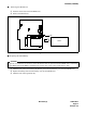
(3) Switch Settings
Note 1:
Set the groove on the switch knob onto the desired switch position.
Note 2:
When the power is on, flip the MB switch to ON (UP position) before plugging/unplugging the circuit
card.
Switch Settings
SWITCH
NAME
SWITCH
NUMBER
SETTING
POSITION
FUNCTION CHECK
SENS
(Rotary SW)
Note 1
4 - F
Set the switch to match the AP Number (04 - 15) to be set by CM05.
0 - 3 Not used
MB (Toggle SW)
Note 2
UP For make-busy
For normal operation
SW
(Piano Key SW)
1
ON For make-busy No. 0 circuit
For normal operation
2
ON For make-busy No. 1 circuit
For normal operation
3
ON For make-busy No. 2 circuit
For normal operation
4
ON For make-busy No. 2 circuit
For normal operation
5
Not used
6
7
8 Always set to ON
AP NO.
SW NO.
1004 05 06 07 08 09 11 12 13 14 15
456789ABCDEF
ON
DOWN
ON
OFF
4
3
2
1
5
6
7
8
OFF
OFF
OFF
OFF
OFF
OFF
OFF
ON