FCC Warning Class B Computing Device Information to the User This equipment has been tested and found fo comply with the limits fo a class B digital device pursuant to part 15 of FOC Rules. These limits arc designed © provide reasonable protection against karakul interference ia 8 residential install ration. This equipment generates, uses, and can radiate radio frequency carapace and, i€ not installation and used in accordance with the instructions, may cause harmful interference 10 idiom communications.
NOTICE This equipment has been tested and found to comply with the limits for a Class B digital device, pursuant to Part 15 of the FCC Rules, These limits are designed to provide reasonable protection against harmful interference ina residential installation. This equipment generates, uses and can radiate radio frequency energy and, if not installed and used in accordance with the instructions, may cause harmful interference to radio communications.
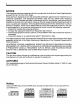
HEED THE FOLLOWING Read the operating instructions carefully before using the unit and be sure to use it properly. After reading the instructions, store them in an easily accessible place so they can be consulted whenever necessary. WARNING B Continued use should there be an irregularity (smoke, abnormal smell or sound, etc.) will lead to fires or electric shocks. If there should be an irregularity, immediately turn off the power of the computer on which the unit is installed and request servicing.
CAUTION Set the volume to the minimum before turning on the power, Sudden bursts of loud sound could result in hearing impairment. Do not store or use the unit in extremely hot places or places where the humidity fluctuates greatly. Doing so could lead to fires or electric shocks. Do not store or use the unit in places exposed to direct sunlight or near equipment that generates heat. Doing so could lead to fires. Do not place the unit on unsteady tables, slanted surfaces or other unstable surfaces.
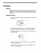
Cautions Cleaning To clean the drive, wipe it with a soft, damp cloth, using mild detergent if necessary. Please avoid using solvents such as benzine or paint thinner. This can cause color charges or deformation of the CD-R/ RW drive. E Handling the Disc + Do not touch the data side of the disc (the side of the disc with no label or printing). « Do not apply paper labels or write on any part of the disc, data side or label side. Do not use the disc leaved a mark strip paper labels.
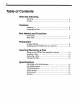
Table of Contents Heed the following Warning . 3 Caution . 8 Cautions Cleaning Handling the Disc Part Names and Functions Front 7 Rear View Preparation Jumper Setting Installing the drive in a host PC Inserting/Removing a Disc Using the Drive Installed Vertically .. inserting a Disc Removing a Disc. Emergency Eject Specifications & CD-ROM Section. Section... CD-ROM Section Audio Section. Environment.
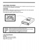
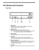
Part Names and Functions Front View 1 Phones Jack This jack is used to connect a set of headphones. Please use headphones with a stereo mini-jack plug. 2 Volume Control This control is used to adjust the headphone volume. NOTE: This control has no effect on the audio output from the LINE QUT connector on the back of the drive. 3 BUSY Indicator This indicator lights umber while data is being read and written. 4 Tray Panel This panel prevents dust from entering the drive.
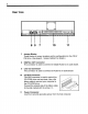
Rear View eye] oo] [Terri (coo Jumper Blocks These blocks of jumper locations set the configuration for the CD-R/ RW drive. (See page 9, “Jumper Setting” for details.) 8 DIGITAL QUT Connector This connector is used to connect CD Digital Audi to an audio board. 9 Line Out Connector This connector is used to connect CD-Audi to an audio board. 10 VO BUS Connector This BUS connector is used to control the drive and sent data. Use a flat ribbon cable to connect your computer to the drive.
Preparation Jumper Setting A jumper consists of a pair of pins and a connector which fits over the pins. When the connector is in place it establishes an electronic link between the pins, which enables the function being controlled by the jumper. If the connector is removed, the electronic link is broken and the function is disabled. JUMPER BLOCK CHISEL —— SLAVE MASTER Jumpers are used to set the drive mode on the IDE interface.
Installing the drive in a host PC Note Refer to the guidebook included with your personal computer for instructions on installing the drive. This chapter gives one example of installation. And, when disconnecting the drive from computer equipment, please wait to remove a couple of minutes until it gets cold. The enclosure may have some points over 60°C. 1. Attach the mounting rails to both the left and right sides of the CD-R/ RW drive. 2.
11 5. Locate a spare power cable in your computer, 8. Connect that power cable to the power connector on the back of the drive.
12 7. Connect the I/O BUS connector on the drive and the IDE connector. Connect the colored stripe side of the cable to the side marked with the arrow (VV). 110 BUS CONNECTOR BUS CABLE ARROW 8. Slide the disc drive and drive into the computer. 9.
13 Inserting/Removing a Disc Using the Drive Installed Vertically When using the drive, in the vertical position, load and unload discs as shown on the diagram below. drive installed vertically drive installed vertically {right side) (left side} Caution Only 12cm discs can be used when the drive is installed vertically. Do not place 8cm discs in the tray when using the drive installed in this way.
Inserting a Disc . 1. Press the Load/Eject button. The disc tray will be ejected. 2. Place the disc in the center of the tray with the label side facing up. 3. Press the Load/Eject button. The disc tray will be retracted. Removing a Disc 1. Crass the Load/Eject button. The disc tray will be ejected. 2. Remove the disc. 3. Press the Load/Eject button. The disc tray will be retracted. WARNING: Do not forcibly push the disc tray in by hand. Doing so may result in damage.
15 Specifications & CD-ROM Section User Data Capacity . 656 M Bytes, Mode 1 {embassies = 1024 x 48 M Bytes, Mode 2 User Data Block. 045 Bytes, Mode 1 and Mode 2 Form 1 2328 Bytes, Mode 2 2328 Bytes, Mode 2 Form 2 Burst Rate . PIO mode 4 support [4A singe word mode 2 support DMA multi word mode 2 support Ultra DMA Mode 2 support Access Time Bisect (1/3 Stroke Read, typical} Hard Error Rate .