
User's Manual
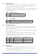
Table Of Contents

D-POS User Manual NE41 07105-02 v1.0
5.3 External control
D-POS has two external inputs which can be connected to closing switches to
control RFID transmission. Input 2 can only be used if D-POS is congured with a
computer, see “5.1 NPU Conguraon” on page 8.
To use input 1 to control RFID transmission (antennas 1 and 2) set DIP switch 2 to
ON. DIP switch 3 determines whether RFID transmission shall be acve when the
input is open or closed.
DIP2 Antennas 1 and 2
ON Antennas are controlled by input 1
OFF Antennas are always acve
Table 7. DIP2 - congure antenna 1 and 2 posion signals
DIP3 Input 1 mode
ON Normally open — antennas acve when input closed
OFF Normally closed — antennas acve when input open
Table 8. DIP3 - Congure input acvaon state
5.4 Idencaon Code
Each D-POS unit must to be idened with a unique code. With the on-board
rotary switches S1-S2 and DIP switches 5 and 6 it is possible to select one of 256
dierent idencaon codes.
When a computer is used to congure D-POS it is possible to choose one of 65000
dierent idencaon codes.
The ID code consists of four hexadeximal digits. The table below shows which
code will be transmied by antenna 1 and antenna 2 depending on the values of
rotary switch S1-S2 and DIP switch 5 and 6.
DIP5 DIP6 Antenna 1 ID code Antenna 2 ID code
OFF OFF S1 S2 0 1 S1 S2 0 1
ON OFF S1 S2 0 1 S1 S2 0 2
OFF ON S1 0 0 1 S1 0 0 1
ON ON S1 0 0 1 S2 0 0 2
Table 9. DIP5 and 6 - antenna posion codes
5.5 Zone Number
Each D-POS unit can be congured to belong to one of 16 zones: 0-9, A-F. The
zone is selected with rotary switch S3. The zone number is used by D-ATOM to
determine if it shall send an alarm or not.
The selected zone number will be used for both antenna 1 and antenna 2.
9