
User's Manual
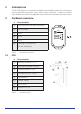
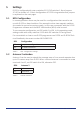
Table Of Contents

D-POS User Manual NE41 07105-02 v1.0
5 Sengs
D-POS is congured with rotary switches S1-S3, DIP switches 1-8 and jumpers
JP1-JP3 as shown in 3.1. Basic conguraon of D-POS using switches and jumpers
is explained on the next pages.
5.1 NPU Conguraon
In some applicaons there may be need for a conguraon that cannot be set
up with D-POS on-board switches. One example is when two magnec switches
are needed to control one antenna each. In this case a computer with the D-POS
Programmer soware and the NEAT USB interface (NPU) must be used.
To use computer conguraon, set DIP switch 1 to ON. In this operang mode,
sengs made with rotary switches S1-S3 while DIP switches 2-8 are ignored.
For more details on how to use D-POS programmer see D-POS and D-ATOM Tech-
nical Handbook, document number NE41 08001-02.
DIP1 Conguraon
ON Computer conguraon
OFF On-board switches
Table 5. DIP1 - Conguraon sengs
5.2 Antenna 2 acvaon
Antenna 2 can be used to extend the coverage area or for a second separate door
up to 10 meters away from D-POS. When a second antenna is connected to screw
terminals 4 and 5, set DIP switch 4 to ON, otherwise OFF.
DIP4 Antenna 2
ON Acve
OFF Not acve
Table 6. Acvate antenna 2
8