
User's Manual
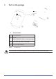
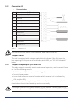
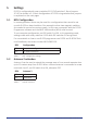
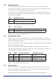
Table Of Contents

D-POS User Manual NE41 07105-02 v1.0
3.2 Connector J1
# Denominaon
12 Output, Normally Closed
11 Output, Normally Closed
10 Ground
9 Input 2/Sync
8 Input 1
7 Ground
6 12-24 V
DC
input
5 Common 2
4 D-POS ANT 2
3 LOOP Antenna
2 Common 1
1 D-POS ANT 1
Table 4. Connector J1
Only use D-POS ANT (NEAT Ferrite Antenna), art#: NE31 07030-01.
3.3 Tamper switch
The unit is equipped with a tamper switch which indicates if the lid is open by
both opening the Output as well as blinking with LED3, see “3.5 LED Indicaon”
below.
3.4 Tamper relay output (#11 and #12)
This relay output is normally closed under normal operaon, and is opened if one
or all of the following occurs:
• The lid is opened (the tamper switch is trigged)
• The unit looses power.
• One or both antennas cease to funcon (which antenna is it is indicated by
LED1 and/or LED2).
The output is open during boot up, which normally takes a second or so, but is
closed when the unit has booted up and runs normally.
The tamper relay will not indicate broken wire for antenna 1 when jumper JP1 is
mounted or for antenna 2 if used with a LOOP with jumper mounted on the LOOP.
6