
- NDC User's Guide Network Device HWB3163

9
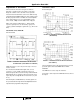
Test Point J
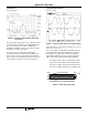
IF Receive Signal:
The intermediate frequency (IF) receive signal is the down-
converted receive signal prior to the SAW bandpass filter.
The center frequency of this signal is 374MHz with a
bandwidth of 17MHz. The power of this signal is directly
dependent on the input signal power.
Note that the spurious signal visible below the DS
spectrum’s frequency is a harmonic of the 44MHz clock.
Much of this level is due to stray pickup in the 500Ω RF
probe because of the relatively low signal level present. As
such, it will have no influence on receiver performance.
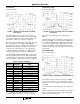
Test Point K-K1 and L-L1
Receive I and Q:
NOTE: BPSK mode is used for the plots in this figure; as such, I and
Q are inverse of each other.
The receive In-phase and Quadrature (I and Q) signals are
the demodulated lowpass-filtered data that are coupled to
the HFA3861. The output levels of these two signals are
approximately 500mV
P-P
. As these are balanced signals,
data is taken using a Tektronix P6247 Differential Probe.
• Test point K for RXI+ signal is at the 0Ω jumper, R19.
• Test point K1 for RXI- signal is at the 0Ω jumper, R23
• Test point L for RXQ+ signal is at the 0Ω jumper, R27
• Test point L1 for RXQ- signal is at the 0Ω jumper, R29.
FIGURE 10. IF RECEIVE SIGNAL PRIOR TO SAW FILTER
(TEST POINT J)
FIGURE 11. RECEIVE I AND Q SIGNALS (TEST POINTS K AND L)
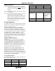
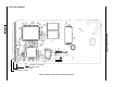
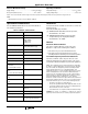
PIN 1
PIN 35
PIN 34
PIN 68
TOP (LED, THIS SIDE)
BOTTOM
VIEW, LOOKING INTO 68 PIN FEMALE CONNECTOR
3V KEY
FIGURE 12. EDGE VIEW, PCMCIA CARD
Application Note 9864