
Tus neeg siv phau ntawv

- 95 -
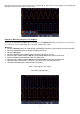
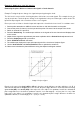
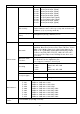
Example 6: Video Signal Trigger
Observe the video circuit of a TV, apply the video trigger and get the stable video output signal display.
9. Troubleshooting
1. The oscilloscope is switched on, but no display appears.
Check that the power is connected correctly.
Check that the fuse next to the mains input socket has not blown (the cover can be prised open with a flat-
blade screwdriver).
Restart the unit after carrying out the above checks.
If the problem persists, please contact your dealer so that we can help you.
2. After capturing the signal, the waveform is not displayed on the screen.
Check that the probe is correctly connected to the electrical line of the signal.
Check that the signal line is correctly connected to the BNC socket (namely the channel connection).
Check that the probe is correctly connected to the object to be measured.
Check if the object to be measured emits a signal (the problem can be solved by connecting the channel that
emits the signal to the faulty channel).
Perform signal acquisition again.
3. The measured voltage amplitude value is 10 times or 1/10 of the actual value.
Make sure that the damping factor for the input channel and the damping factor of the probe match.
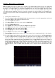
4. A waveform is displayed, but it is not stable.
Check that the source in the TRIG MODE menu corresponds to the signal channel used in practice.
Check the trigger type: the ordinary signal selects edge trigger mode and the video signal selects video
trigger mode. If alternating trigger was selected, the trigger levels of both channel 1 and channel 2 should be
adjusted to the correct position. Only when the correct trigger mode is applied can the waveform be displayed
stably.
Try changing the trigger coupling to RF suppression and LF suppression to smooth out the high-frequency
and low-frequency noise triggered by the interference, respectively.
5. No reaction of the display to pressing the Run/Stop button.
Check if Normal or Signal is selected in the TRIG MODE menu for Polarity and the trigger level exceeds the
waveform range. If this is the case, set the trigger level to the centre of the display or set the trigger mode to
Auto. The above setting can be done automatically by pressing the Autoset button.
6. The waveform display seems to slow down after increasing the average value in Acquire mode.
(see "Setting up the scanning function") or a longer duration was set for Persist under Display (see "Afterglow").
This is normal because the oscilloscope has to process many more data points.
(1) Press the trigger menu button to display the trigger menu.
(2) Select the first menu item in the bottom menu. Select Single in the right-
hand menu.
(3) Select Video as the mode in the left menu.
(4) Select Source in the bottom menu. Select CH1 in the right menu.
(5) Select Modu in the bottom menu. Select NTSC in the right menu.
(6) Select Sync in the bottom menu. Select Field in the right menu.
(7) Turn the vertical scale, vertical position and horizontal scale knobs to get
a correct waveform display.