
Tus neeg siv phau ntawv

- 6 -
3. quick guide
This chapter covers the following topics:
Structure of the oscilloscope
Introduction to the user guidance
Testing before commissioning
Function test
Probe compensation
Probe attenuation
Safety when using the scanner
Carrying out the self-calibration
Introduction to the vertical system
Introduction to the horizontal system
Introduction to the trigger system
Introduction to touch screen operation
Structure of the oscilloscope
When you receive a new oscilloscope, the first thing you should do is familiarise yourself with its control
panel. This chapter provides a simple description of the operation and functioning of the oscilloscope's control
panel so that you can quickly become familiar with its use.
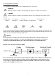
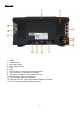
Front
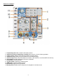
The oscilloscope has a simple control panel with rotary knobs and function keys that can be used to set the
various functions for performing basic operations. The functions of the knobs are very similar to those of other
oscilloscopes. The 5 keys (F1 ~ F5) to the right of the screen or in the row below the screen (H1 ~ H5) are
menu selection keys that allow you to set the different options for the current menu. The other keys are
function keys that allow you to enter different function menus or access a specific function directly.
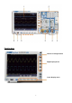
1. Display range
2. Control (push buttons and rotary switch) Range
3. Probe compensation: Measuring signal (5 V / 1 kHz) Output
4. EXT trigger input
5. Signal input sockets (2 to 4, depending on model)
6. Copy button: Saves waveform directly
7. USB host port: For connecting an external storage medium
8. Power button ON/OFF: Red = unit switched off ; Green = unit switched on
Below the display are the H1 - H5 keys for operating the lower menu row. To the right of the display are
the F1 - F5 keys for controlling the (superimposed) menu control on the right side of the screen.