
Tus neeg siv phau ntawv

- 45 -
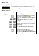
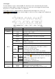
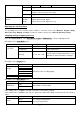
2. I2C trigger
The I2C Serial Bus consists of SCL and SDA. The transmission rate is determined by SCL and the
transmission data by SDA. As shown in the picture, the oscilloscope can be triggered to Start, Restart,
Stop, Ack Lost, a specific device address or a data value.
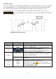
In I2C trigger mode, the setting information is displayed at the bottom right of the screen, e.g.:
indicates that the trigger is in I2C mode, CH1 as trigger level is 0.00mV and
CH2 as trigger level is 0.00mV.
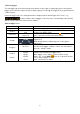
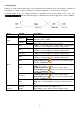
Menu
Setting
Description
Bus Type
I2C
Set vertical bus type as I2C triggering
Source
CH1
CH2
Set CH1 as SCL or SDA
Set CH2 as SCL or SDA
When
Start
Triggers when SDA data passes from High to Low while
SCL is High
Restart
If another start state occurs before a stop state
Stop
Triggers when SDA data passes from Low to High while
SCL is High
Ack Lost
Triggers when SDA data is "High" during a confirmation of
the SCL clock position.
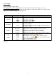
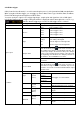
Address
Triggers a read or write bit when the set address is hit.
Adr
Format
Addr Bits
Set bit address aud 7, 8 or 10
Set address according to the set bit address. Address
range is 0-127, 0-255, 0-1023
Set data direction to Read or Write
Note: If address bit is set to 8, this is not available
Address
Direction
Data
Searches for the preset data value of SDA and triggers on
the falling edge of the SCL, on the last bit of the data range
Data
Format
Byte
length
Set data byte length, available is 1-5.
Use the multi ( ) knob or the touch control to set the byte
length.
Select data bit, range from 0 to (byte length *8-1).
Set data to H, L or X (H or L).
Set all data bits as specified values.
Current
Bit
Data
All Bits
Addr / Data
Triggers when address and data conditions are met at the
same time
Fashion
Holdoff
Car
Normal
Single
Capture waveform even if no trigger occurs
Capture waveform when a trigger occurs.
When trigger occurs capture a wave and then stop it